

The R1 R2 test is one of the most informative measurements taken during the dead testing sequence of an electrical installation. It confirms the continuity of protective conductors and gives the electrician the data needed to verify circuit integrity, calculate earth fault loop impedance, and satisfy the requirements of BS 7671:2018+A4:2026. For working electricians and apprentices building toward competence, understanding what the reading actually tells you matters far more than simply recording a number on a schedule of test results.
This guide breaks down the purpose of the test, the method, the expected values, and how to interpret results correctly and safely.
What R1 and R2 Actually Measure
This is a continuity test carried out on a final circuit while it is dead. The two values represent specific conductors:
- R1: The resistance of the line (phase) conductor.
- R2: The resistance of the circuit protective conductor (CPC), usually the earth conductor.
Measured together, R1 + R2 gives the total resistance of the line conductor and the CPC from the origin of the circuit to the furthest point. This combined figure confirms that the protective conductor is continuous and correctly connected throughout the circuit.
Continuity of protective conductors is a mandatory dead test under Regulation 643.2.1 of BS 7671, carried out during initial verification and every periodic inspection.
R1 R2 Test Versus the R2-Only Test
Apprentices often confuse two related checks, so it is worth separating them clearly:
- R1 + R2: The line conductor and CPC are linked at the board, and the reading gives their combined resistance. This feeds directly into your Zs calculation.
- R2 only: Measured on its own, usually with a wander lead from the main earthing terminal to the CPC at each point. This confirms CPC continuity where you do not need the line contribution, such as testing bonding or a separate protective conductor.
Both prove the CPC is sound. The difference is whether you also capture the line conductor for the loop impedance sum.
Why the Test Matters
The primary purpose is to confirm the continuity of protective conductors, which underpins automatic disconnection of supply under fault conditions. If the CPC is broken, high in resistance, or incorrectly terminated, the protective device may not operate within the required disconnection time, leaving exposed conductive parts dangerous during a fault.
The reading also feeds directly into loop impedance verification. The measured R1 + R2 value is used to establish the earth fault loop impedance (Zs) for the circuit:
Zs = Ze + (R1 + R2)
Here, Ze is the external earth fault loop impedance measured at the origin. By adding the measured R1 + R2 to Ze, the electrician can calculate the expected Zs without carrying out a live loop test at every point. That is useful where live testing is impractical or where RCD nuisance tripping would interfere.
The calculated Zs is then compared against the maximum permitted values in BS 7671 Tables 41.2 to 41.5 for the relevant protective device type and rating. If the calculated figure exceeds the maximum, disconnection times cannot be guaranteed and the circuit does not comply.
Safe Isolation Comes First
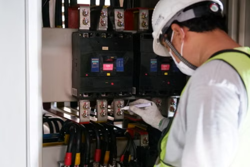
No continuity testing takes place on a live circuit. Before any measurement:
- Isolate the circuit: Secure the isolation so it cannot be inadvertently re-energised, and lock off where possible.
- Prove dead correctly: Use an approved voltage indicator to GS38, verified against a proving unit before and after the check. Probes should have finger guards and no more than 4mm of exposed metal at the tips, preferably 2mm.
- Null your leads: Zero the test leads on the low ohms range before testing, or lead resistance will inflate every reading.
Failing to account for lead resistance can push a marginal circuit into apparent non-compliance, or mask a genuine fault. Getting isolation and nulling right is what makes the rest of the test trustworthy.
How the Test Is Carried Out
There are two recognised methods for a standard radial circuit, and the choice depends on the circuit and site conditions.
Method 1: The Wander Lead Approach
A temporary link connects the line conductor to the CPC at the distribution board. The electrician then measures the resistance between line and earth at each point on the circuit, such as socket outlets, lighting points, and switches. The reading at the furthest point gives the full R1 + R2 value.
This method confirms continuity and correct polarity at every accessory tested, which makes it thorough and well suited to verifying a new installation.
Method 2: The Cross-Connect Method
The line and CPC are linked together at the distribution board, and readings are taken across the two conductors. This approach is efficient but assumes terminations are sound throughout, so it is often paired with additional checks.
Whichever method you use, remove the temporary link and reinstate the circuit correctly before energising. Leaving a link in place is a serious error.
Ring Final Circuits Are Different
A ring final circuit is not tested the same way as a radial, and this trips up a lot of people. Regulation 643.2.1 requires an extra step because you have to prove the ring is actually a ring:
- Step one: Identify both legs at the consumer unit and measure the end-to-end resistance of each conductor in turn, giving r1 (line), rn (neutral), and r2 (CPC).
- Step two: Cross-connect the conductors and take readings at each socket outlet.
Done correctly, the R1 + R2 value should read roughly the same at every outlet, at approximately (r1 + r2) divided by 4. A reading that climbs at one point suggests an interconnection, a break in the ring, or a spur mistaken for part of the ring.
Understanding the Reading
A number on its own means little without something to compare it against. There is no single pass or fail figure.
For any circuit, the expected R1 + R2 can be calculated from the conductor cross-sectional areas, the cable length, and the resistance per metre of the conductors. Published reference values for copper conductors let you predict a target figure, and a measured value close to that target indicates sound, continuous conductors.
Consider what different readings suggest:
- Close to the calculated value: Good continuity and correct conductor sizing.
- Significantly higher: A high resistance joint, a loose termination, corrosion, or a damaged conductor.
- Open or infinite: A break in continuity, a missing link, or a disconnected conductor.
- Far lower than expected: A parallel path, such as the CPC touching other earthed metalwork, which can disguise a genuine continuity problem.
Temperature affects conductor resistance too. Readings taken cold differ from those at working temperature, so the R1 + R2 value is corrected for temperature before it is added to Ze for the Zs calculation. Guidance material such as IET Guidance Note 3 sets out the correction factors used.
Common Errors and How to Avoid Them
A few recurring mistakes undermine the reliability of the result:
- Skipping the null: The most frequent error, adding a small but meaningful resistance to every reading.
- Testing before proving dead: A serious safety failure that must never happen.
- Poor probe contact: Painted or corroded terminals produce inflated readings mistaken for faults.
- Parallel earth paths: Extensive bonding or metallic containment can give artificially low readings that hide a broken CPC.
A disciplined routine of isolate, prove dead, null the instrument, test methodically, and cross-check against calculated values will catch most of these.
Understanding the R1 R2 test takes practice as well as technical knowledge. TradeFox offers practical electrical simulations that let you revisit key skills and build confidence at your own pace.
Recording and Compliance
The R1 + R2 values, along with the derived Zs, are recorded on the schedule of test results that accompanies an Electrical Installation Certificate, Minor Electrical Installation Works Certificate, or Electrical Installation Condition Report. Accurate recording is a professional requirement, and the figures form part of the evidence that the installation meets the standard. Note that the model forms were updated under Amendment 4, so always work to the current schedule.
For anyone working toward inspection and testing qualifications, competence here is a core assessed skill. It is a genuine safety verification, not a box-ticking exercise.
Key Takeaways
The R1 R2 test verifies the continuity of the line conductor and protective conductor across a final circuit, confirms the CPC is sound, and provides the R1 + R2 value used to calculate earth fault loop impedance. Carried out dead, proved dead to GS38, nulled correctly, and interpreted against a calculated expected value and the BS 7671 maximum Zs tables, it gives clear evidence of circuit integrity and compliance. Read properly, the number is not just a figure on a certificate. It is confirmation that the safety of the installation can be relied upon.