Cold patches at the top of a panel, a gurgling rad in the back bedroom, a boiler that runs but the upstairs circuit barely warms. Every engineer knows the call. Sometimes it really is trapped air and a five-minute bleed sorts it. Sometimes it isn’t. Knowing the difference is what separates a competent service from a callback in three weeks when the customer’s mid-section radiator is still cold and they’ve started losing pressure overnight.
This is a working guide on how to bleed a radiator properly, top up a sealed system the right way, diagnose genuine air locks, and recognise the symptoms that point to magnetite sludge rather than air. It assumes you’re working on UK domestic wet central heating systems, and that you’re either Gas Safe registered or working towards trade qualification.
When A Bleed Is Actually The Right Call
Before touching a vent key, confirm the symptom matches the diagnosis. Air collects at the highest point of a radiator because it’s less dense than water, so a true air-locked radiator presents with a cold top and a warm bottom. The flow is reaching the rad and circulating through the lower section, but the upper portion is displaced by gas.
If the pattern is reversed, you’re not looking at air. The diagnostic shorthand:
- Cold at the top, warm at the bottom: Air, bleed it.
- Cold at the bottom, warm at the top: Sludge accumulation, clean the system.
- Cold across the middle with warm edges: Sludge or restriction, not air.
- Multiple radiators on one circuit losing output progressively: Sludge or circulation issue, not a bleeding job.
A genuine air-lock candidate usually has an obvious cause. Recent work on the system, a drain-down and refill, a topped-up pressure after a leak repair, a new radiator swapped in, or an open-vented system where the feed and expansion cistern has been drawing air in through the vent pipe due to pump over-run.
The Method: Step-By-Step
The technique for how to bleed a radiator is straightforward, but the sequence matters when you’re working through a whole property.
Step 1: Isolate The System
Switch off the boiler at the programmer and isolate the electrical supply at the fused spur. Working live on a system where you may end up touching the pump or removing components is dangerous. Allow the system to cool fully. Bleeding a hot, circulating system pushes scalding water out under pressure and prevents air from settling at the high points where you need it.
Step 2: Start At The Lowest Point
On a multi-storey property, begin with the ground floor radiator furthest from the boiler and progress floor by floor, finishing at the highest point. Usually a heated towel rail or top-floor radiator. Air migrates upward, so working bottom-to-top pushes it out in the correct direction.
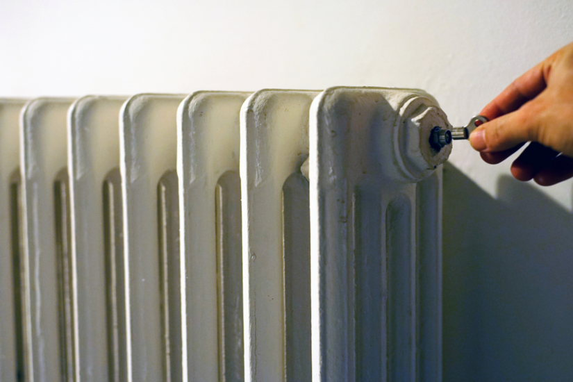
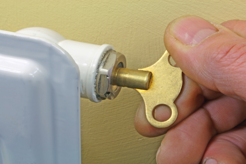
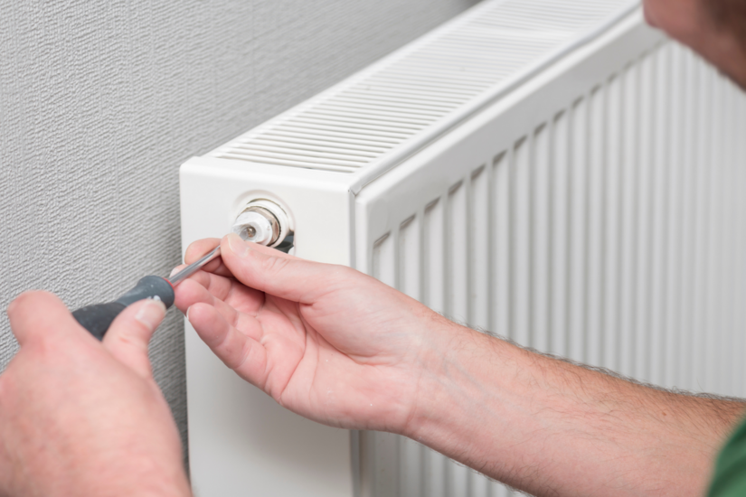
Step 3: Position The Tools
Engage the bleed key, or flat-head screwdriver on modern slot-type vents, on the vent valve at the top corner of the rad. Hold a lint-free cloth and a small container underneath.
Step 4: Open The Valve
Open the valve a quarter to half turn. No more. You’re listening for the hiss of escaping air. Keep going until the hiss stops and a steady bead of water appears, then close immediately. Over-rotating risks shearing the spindle on older brass vents, particularly on radiators that haven’t been touched in years.
Step 5: Read The Water
This is the diagnostic step most engineers under-use. The water coming out tells you the condition of the system:
- Clear or pale straw: Healthy.
- Dark grey or black with a metallic odour: Magnetite present, system needs investigation.
- Brown or rust-tinted: Oxidation, often points to oxygen ingress.
If you’re getting black water from the bleed valve, the job is no longer a bleed. Note it for the report and discuss with the customer.
Step 6: Check Pressure And Refire
On a sealed system, every bleed drops the system pressure. Once you’ve worked through all radiators, the gauge will likely sit below the 1 bar minimum and need topping back up via the filling loop. Bring the system back up to operating temperature and check each radiator for even heat distribution top-to-bottom. If a previously cold-topped rad is now warm throughout, the job is done.
Pressure Top-Up: Doing It Properly
A sealed system relies on the expansion vessel and a static fill pressure to maintain circulation. Most modern combi and system boilers specify a cold fill pressure between 1.0 and 1.5 bar, with the pressure relief valve typically set to operate at 3 bar in line with BS EN 12828 and standard UK manufacturer specifications. Always check the manufacturer’s commissioning data for the specific appliance. Worcester, Vaillant, Ideal and Baxi all have slightly different stated ranges.
Filling Loop Compliance
The filling loop is a Water Regulations matter, not just a convenience. Under the Water Supply (Water Fittings) Regulations 1999, a domestic central heating circuit is typically categorised by the water undertaker as Fluid Category 3 risk where only approved inhibitors are used. The final decision on category rests with the local water undertaker, and higher protection may be required on commercial or non-domestic systems where Category 4 applies.
For a Category 3 domestic heating circuit:
- A WRAS-approved double check valve conforming to BS EN 13959 must be installed at the point of connection.
- The installation must comply with BS EN 1717, the governing standard for backflow protection.
- Best practice is for the flexible hose to be disconnected at one end when not in use.
- Permanently connected filling loops without proper backflow protection are non-compliant.
Top-Up Procedure
- Confirm the boiler is off and the system is cold. Topping up hot reads false-high on the gauge once it cools.
- Check both ends of the filling loop are properly connected and the hose is sound.
- Open the first valve slowly, then the second. You should hear water flowing.
- Watch the gauge. Stop at 1.0 to 1.2 bar cold. Don't chase 1.5 bar on a cold fill, because thermal expansion will push you toward the upper end of normal working range when the system heats.
- Close both filling loop valves. Disconnect one end of the flexible hose.
- Refire and verify pressure stability across a full heating cycle.
Over-Fill And PRV Behaviour: Two Separate Issues
A common misconception is that over-filling causes the pressure relief valve to discharge. These are actually two distinct concerns:
- Cold over-fill is undesirable because it reduces the expansion headroom your vessel can absorb. The hot working pressure will then sit higher than designed.
- PRV discharge at 3 bar indicates either a genuine over-pressure event or a failed component.
- The most common cause of PRV weeping is a punctured or under-charged expansion vessel diaphragm, not over-filling. Recharge the vessel air side to manufacturer specification before assuming the PRV itself is faulty.
If you’re topping up the same system more than once in a fortnight, you have a leak. That might be a visible drip at a TRV or compression joint, a slow weep from the PRV discharge pipe (check the tundish or external discharge point), a punctured expansion vessel diaphragm, or a hairline crack in the heat exchanger. Don’t keep filling. Diagnose.
Diagnosing An Air Lock Properly
An air lock isn’t always solved at the radiator vent. On sealed systems, air can collect in the pump, the auto-air vent at the boiler, the heat exchanger, or in horizontal pipe runs that sag.
Symptoms Pointing To A Trapped Air Lock
- A radiator that bleeds clean but stays cold at the top after multiple attempts.
- Gurgling or kettling noises from pipework when the pump runs.
- The pump running but circulation barely moving. Check by feeling flow and return pipe temperatures at the boiler. They should differentiate by around 10 to 20 degrees on a typical condensing setup.
- A whole circuit cold while the boiler shows normal flow temperature.
Staged Resolution For A Stubborn Air Lock
For a persistent air lock, work through the system in order:
- Bleed all radiators again, lowest to highest.
- Check and operate the automatic air vent on the boiler. Most have a screw cap that needs loosening one turn during commissioning and re-tightening when air stops escaping.
- Bleed the pump via its central screw if accessible. Note that many modern integrated boilers have an internal pump that is not user-serviceable. In that case the appliance's own auto-air vent does the job, or the system needs venting at higher points in the pipework.
- On persistent cases, drop the system pressure, isolate the loop, and use a sealed-system air separator or vent at the highest accessible point.
On open-vented systems, recurring air at the radiators often indicates pump over-run drawing air down through the open vent. That’s a design or pipework configuration issue, not a bleeding problem. Check the relative position of the cold feed and open vent connections on the flow pipe, and verify the pump head is appropriate for the system.
Signs You're Dealing With Sludge, Not Air
This is where engineers earn their fee. Magnetite sludge is iron oxide produced by corrosion within the system. It’s heavier than water and settles at the lowest point of radiators and pipework, creating the opposite symptom to air: cold at the bottom of the radiator with warmth at the top.
Clear Indicators Of Sludge
- Cold spots at the bottom or centre of radiators. Bleeding does nothing because there's no air to release. Flow is being restricted by deposits inside the rad.
- Black or grey-black water at the bleed point. Healthy inhibited system water is clear or pale. Black water means magnetite is suspended throughout the circuit.
- A heavily loaded magnetic filter. If the property has an in-line filter and it's loading up quickly between services, the system is actively corroding.
- Boiler noise. Kettling, banging, or rumbling from the heat exchanger often indicates debris and limescale build-up restricting flow through the primary heat exchanger.
- Cold radiators in specific zones. Sludge tends to accumulate first in radiators with the lowest flow rates, usually the longer runs or those at the end of a circuit.
- Pump failure or stiff TRVs. Magnetite is erosive in suspension and binds moving parts when settled around them.
What BS 7593:2019 Requires
Under BS 7593:2019, the Code of Practice for the preparation, commissioning and maintenance of domestic central heating and cooling water systems, a sludged system requires a recognised cleaning method before any new appliance is fitted. The standard recognises three options:
- Powerflushing
- Mains pressure cleaning
- Gravity cleaning
The cleaning chemical is dosed and circulated, the system is flushed until the water runs clear, a permanent in-line filter is fitted, and a corrosion inhibitor is dosed at the correct concentration. BS 7593:2019 also recommends annual inhibitor level checks and re-dosing every five years, or a verified laboratory water test in lieu of re-dosing.
The Part L Position
BS 7593:2019 is a code of practice. It is not, in itself, a statutory instrument. However, Approved Document L of the Building Regulations references BS 7593 as the recognised compliance route for the commissioning of wet central heating systems on new and replacement boiler installations. In practical terms, an installer who fits a new boiler without cleaning, dosing, fitting an in-line filter and recording commissioning data on the Benchmark checklist will struggle to demonstrate Part L compliance. The standard’s “should” language is recommendation; Part L is the regulatory hook that makes it the working compliance pathway.
Safety, Records And Customer Communication
A few non-negotiables when working on heating systems.
Electrical And Mechanical Safety
- Isolate the electrical supply at the fused spur before working on pumps or removing components.
- System water can be hot enough to scald hours after shutdown on a well-insulated property. Treat every drain-down with the assumption it's still warm.
- Eye protection during bleeds and drains. Gloves when handling system water. Magnetite is an irritant and inhibitors are not drinking-water grade.
COSHH Compliance
Under the Control of Substances Hazardous to Health Regulations 2002, employers have a duty to assess risks from chemical products including cleaners, inhibitors and biocides. Manufacturer safety data sheets must be available on site. This applies whether you’re a sole trader or working for a firm.
Gas Safe Scope
If the work touches the gas appliance, for example draining for a heat exchanger inspection or any work on the gas-carrying envelope, that work falls under the Gas Safety (Installation and Use) Regulations 1998. It must be carried out by a Gas Safe registered engineer working within the categories on their ACS qualifications. Draining the system in isolation is not in itself notifiable, but work on the appliance is.
PRV Discharge Pipework
The pressure relief valve discharge pipe must not be capped, blocked, or modified. Under the current Gas Industry Unsafe Situations Procedure, a non-compliant discharge arrangement is classified as Immediately Dangerous. If you find one on a service visit, the appliance must be turned off, the situation made safe, and the issue reported in line with the published procedure.
Records
Record system water condition, inhibitor concentration where tested, filter condition, and any sludge findings on the job sheet. If you’ve recommended a powerflush or chemical clean and the customer has declined, document the decline in writing. It protects the customer and it protects you when a heat exchanger fails inside warranty and the manufacturer asks about water quality compliance.
Good heating work starts with safe habits, clear records, and confidence on the job. Build practical skills through TradeFox and keep improving the standards you bring to every installation and service visit.
Summary For The Apprentice
If you take one thing away: the act of bleeding a radiator is the easy part. The skill is reading what the bleed water and the symptom pattern are telling you about the system underneath.
- Cold at the top means air, bleed it.
- Cold at the bottom means sludge, clean it.
- Pressure that won't hold means a leak, find it.
- Black water at the vent means the system is failing chemically, dose it.
- A callback within a fortnight means you missed something the first time.
Get those diagnostic checks right and you’ll spend less time on returns and more time on properly billed remedial work.