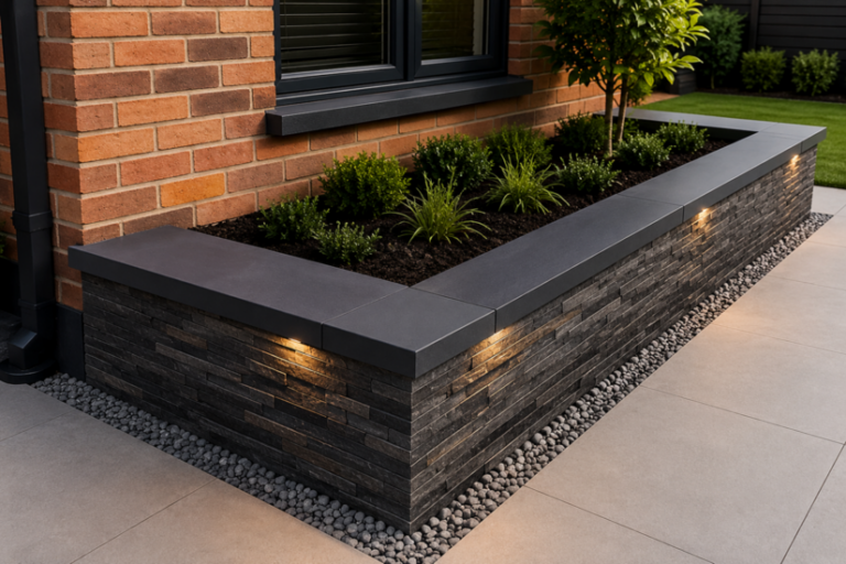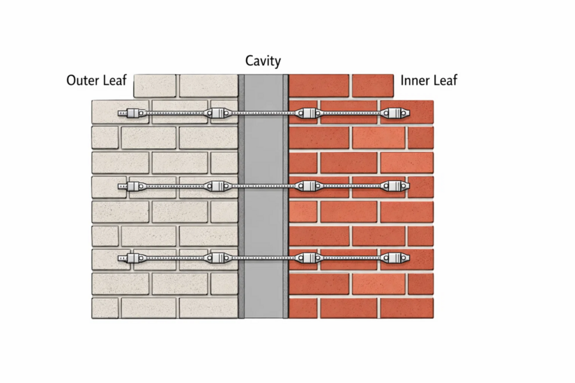
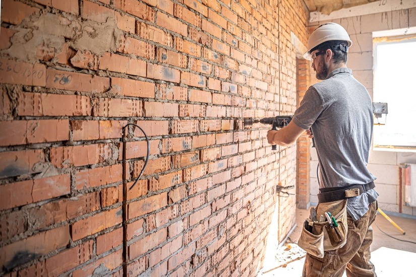
Cavity wall construction relies entirely on the mechanical connection between the internal load-bearing leaf and the external masonry skin. Wall ties perform this vital structural duty. They transfer static and dynamic loads across the cavity while simultaneously preventing moisture ingress.
Getting the installation wrong during the superstructure phase guarantees structural instability, failed building control inspections, and severe financial penalties for the contractor. This technical guide outlines the strict United Kingdom regulatory patterns, the specific effects of modern cavity dimensions, and the diagnostic signs of failure that tradesmen must recognize on site.
Building Regulations And Baseline Standards
Approved Document A of the UK Building Regulations and PD 6697 provide the definitive legal framework for masonry construction. These specific documents dictate exactly how many ties are required per square meter to withstand anticipated wind loads and maintain long-term structural integrity.
Professional bricklayers and site managers must treat these dimensional parameters as absolute legal minimums rather than rough guidelines. Deviating from these codes leaves the contractor legally liable for any subsequent structural collapse.
Standard Wall Tie Spacing Patterns
The Standard Grid
The general rule for standard domestic masonry requires a minimum of 2.5 ties per square meter of wall area. The standard wall tie spacing dictates a maximum horizontal distance of 900mm and a maximum vertical distance of 450mm between ties.
Installers must lay the ties in a staggered, diamond pattern rather than a square vertical grid. This staggering ensures an even distribution of stress and tension across the entire masonry panel.
Unbonded Edges And Boundaries
However, the standard pattern changes abruptly at unbonded edges. Around window openings, door frames, movement joints, and at the unbonded edges of gable ends, the structural vulnerability of the masonry increases significantly.
In these specific zones, tradesmen must increase the tie density:
- The vertical distance must be reduced to 300mm at these boundaries.
- Furthermore, the first tie must be installed no further than 225mm horizontally from the open edge.
Failing to increase the density at these critical junctions is a primary cause of localized masonry failure under high wind suction.
Geographical Wind Zones And Exposure Ratings
Assessing Wind Suction Forces
The United Kingdom experiences vastly different weather patterns depending on the specific geographical location and topography. The required installation density is never a universal constant. It is heavily dictated by the local wind exposure rating.
Buildings located in severe exposure zones, such as coastal regions or highly elevated moorland sites, experience significantly higher dynamic wind suction forces compared to sheltered urban developments. Site engineers calculate the basic wind speed for the specific postcode using BS EN 1991-1-4.
Upgrading Structural Specifications
If the wind suction calculation exceeds the structural capacity of standard ties placed at standard intervals, the specification must change. The structural engineer will either:
- Mandate a heavier gauge of tie, such as upgrading from a Type 2 general-purpose tie to a Type 1 heavy-duty masonry tie.
- Calculate a denser wall tie spacing grid.
In extreme wind zones, the vertical and horizontal distances between ties are mathematically reduced to increase the overall structural resistance of the cavity wall. Installers cannot simply assume the standard 900mm by 450mm grid is compliant without consulting the structural drawings specific to that exact site.
The Impact Of Modern Cavity Widths
Thermal Efficiency Requirements
Modern thermal efficiency requirements have drastically changed traditional construction methods. Older properties often feature narrow 50mm cavities. Modern superstructures frequently demand cavities of 100mm, 150mm, or even wider to accommodate high-performance insulation batts.
Specifying The Correct Tie Type
As the cavity widens, the structural performance of the steel tie decreases due to increased bending moments. The correct wall tie spacing must be paired directly with the correct tie specification to counteract this structural weakness. Ties are categorized from Type 1 for heavy-duty applications to Type 4 for light-duty housing applications.
- A Type 4 tie might be perfectly compliant for a standard 50mm cavity in a low-rise domestic build.
- If the architect increases the cavity to 150mm, that exact same Type 4 tie becomes structurally inadequate, regardless of how closely it is spaced.
- The site manager must upgrade to a heavier gauge wire or a specialized heavy-duty strip tie.
Embedment Depth Tolerances
Embedment depth is another critical factor linked directly to cavity width. UK regulations mandate a minimum embedment of 50mm into the mortar bed joint on both the inner and outer leaves.
To guarantee this minimum embedment safely, considering typical site cutting tolerances and minor blockwork variations, professionals routinely specify ties that allow for a 62.5mm or even 75mm embedment. If a tie is too short for the constructed cavity, the embedment is fundamentally compromised.
Managing The Drip Feature
Furthermore, installers must pay strict attention to the drip feature formed into the tie. The drip must be positioned squarely in the center of the open cavity, pointing downwards. This prevents rainwater from bridging the cavity and tracking towards the inner leaf.
If insulation batts push the tie upwards, or if the bricklayer beds the tie sloping towards the internal blockwork, penetrating damp is mathematically guaranteed.
Insulation Retention And Cavity Bridging
Mechanical Restraints For Boards
Modern cavity walls are routinely fitted with partial-fill rigid PIR boards or full-fill mineral wool batts. The tie performs a secondary structural function in these systems. It acts as the mechanical restraint for the insulation material.
Installers must use specially designed retaining clips that snap firmly onto the wire or strip of the tie. These plastic clips force the insulation board tight against the inner blockwork leaf.
If the retaining clips are omitted, the insulation boards can warp and lean across the cavity. This physical movement bridges the air gap, allowing penetrating moisture from the outer brickwork to track directly into the dry insulation and across to the internal plaster.
Preventing Mortar Bridging
When installing rigid insulation, the bricklayer must ensure the chosen wall tie spacing aligns perfectly with the dimensions of the insulation boards.
- Ties must secure the corners and edges of every single board to prevent thermal bowing.
- The installation process must remain immaculately clean.
- Dropping wet mortar down the cavity onto the ties creates a solid bridge.
This mortar bridge entirely bypasses the integrated drip feature, causing severe damp penetration that is incredibly difficult and expensive to rectify post-construction.
Recognizing And Diagnosing Tie Failure
The Chemistry Of Corrosion
Remedial tie replacement represents a massive sector within the UK construction industry. Recognizing the early diagnostic signs of failure allows contractors to specify appropriate intervention before catastrophic collapse occurs.
The most common cause of failure in properties built before 1981 is the corrosion of mild steel ties. The galvanizing process used during this era was often insufficient to withstand the highly alkaline environment of the mortar bed. This chemical reaction accelerates heavily in properties constructed with high-sulphate black ash mortar.
Visual Indicators Of Expansion
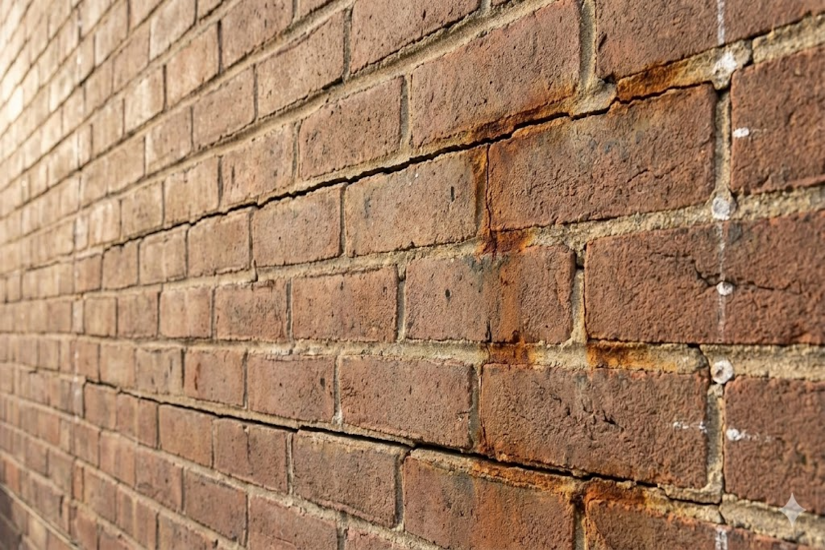
As the steel tie rusts, the iron oxide expands up to seven times the thickness of the original metal. This massive expansion exerts immense vertical pressure on the surrounding masonry. Tradesmen will identify this specific issue by looking for horizontal cracking in the exterior mortar joints.
Because the original installation likely followed a 450mm vertical distance, these horizontal cracks typically manifest every sixth course of standard UK brickwork.
Other visual indicators include bulging external walls. This happens where the outer leaf has completely detached from the inner structure and is bowing outward under its own weight.
In extreme cases of cavity tie failure, the upward expansion of the masonry can actually lift the roof plate. This causes visible distortion at the eaves line and damages the roof trusses.
Remedial Pull-Out Testing And Safe Installation
Neutralizing The Old Fixings
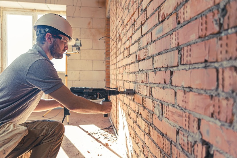
When a site survey confirms structural failure, contractors must execute a highly controlled remedial strategy. Simply drilling and injecting new fixings is never sufficient. The expansive force of the old, rusting steel must be neutralized first.
Tradesmen must locate the existing ties using a specialized metal detector calibrated for masonry. Once located, the brickwork must be carefully chased out to expose the corroded metal. The operative must:
- Physically crop the old tie back deep within the cavity.
- Alternatively, they must fully extract the outer end from the mortar bed entirely.
This permanent physical removal is the only compliant method to stop further rust expansion from lifting the masonry.
Installing Remedial Ties
New remedial ties are then installed at the correct structural grid. Installers utilize either mechanical expansion anchors, helical friction-fit pins, or chemical resin-fixed studs. The selection depends entirely on the condition and load-bearing capacity of the existing substrates.
The installation must be rigorously tested and legally certified to comply with Building Research Establishment Digest 329.
Destructive Vs. Non-Destructive Testing
Professional tradesmen must conduct physical testing on site to verify the holding power of the new fixings. It is highly critical to understand the difference between destructive baseline testing and non-destructive proof testing.
- Initial destructive testing is performed on a tiny sample to determine the ultimate failure load of the chosen substrate.
- However, routine remedial testing across the main wall is strictly non-destructive proof testing.
A calibrated tension meter is attached to the exposed end of the newly installed remedial tie. The operative applies a steady, measured axial pull force to a calculated proof load. This proof load is typically the required working load multiplied by a safety factor. The gauge confirms the fixing holds firm without destroying the surrounding masonry.
These proof tests must be conducted on a representative sample of the installation across the entire elevation. If the chemical resin fails to cure correctly, or if the mechanical expansion anchor slips before reaching the proof load, the gauge will register a failure.
The contractor must then recalculate the structural requirements and potentially switch to a different fixing methodology before building control will issue a final structural sign-off.