Dielectric breakdown is what happens when an insulating material stops insulating and starts conducting, letting current punch through where it was never meant to go. In high-voltage assets such as cables, transformers, switchgear and motor windings, this is the single most common reason insulation fails in service.
For anyone working on or around HV plant, this is not academic. It is the difference between a planned outage and a flashover that puts someone in hospital.
This guide explains the mechanisms behind insulation failure, the conditions that speed it up, the warning signs you can pick up before failure, and the testing and competence duties that sit on your shoulders under UK regulation. It is written for working tradesmen and those training to join the trade, not for DIY work. HV work is reserved for skilled and competent persons, and nothing here changes that.
What is dielectric breakdown?
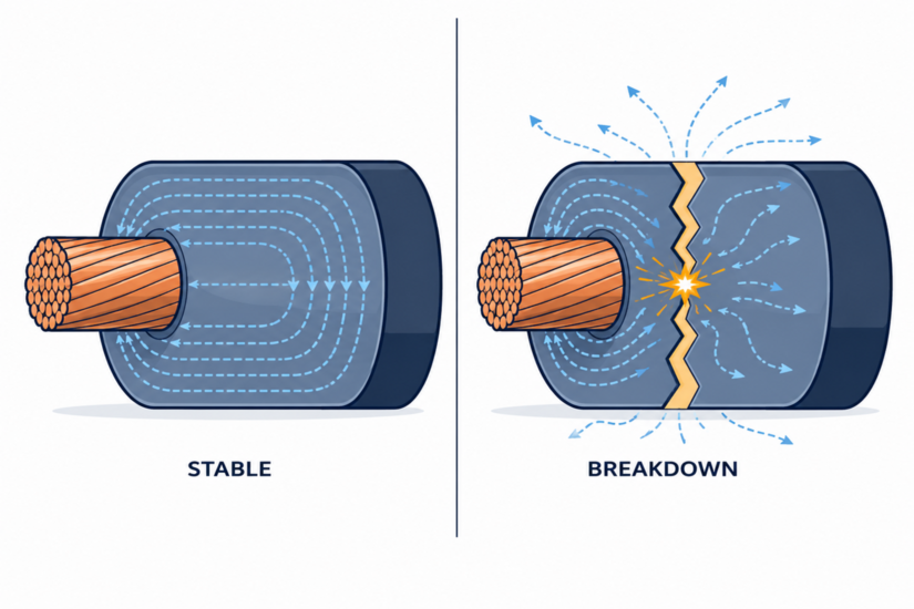
Dielectric breakdown is the point at which an insulating material can no longer withstand the electric field across it and suddenly conducts current. Every insulator has a limit, known as its dielectric strength, usually quoted in kilovolts per millimetre (kV/mm).
Below that limit, the material holds back the voltage. Push past it and the insulation fails, opening a conduction path through the material itself.
In practical terms, insulation around a conductor exists to keep current on its intended path. When breakdown occurs, current finds a new path:
- Conductor to earth
- Phase to phase
- Through the body of the insulation
The result is usually a fault, an arc, heat, and often permanent damage to the asset. It is worth noting that there is no single failure mechanism here. Breakdown can be electronic, thermal, or electromechanical, depending on the material and the conditions, but the end result is the same loss of insulation.
Where BS 7671 stops and EAWR takes over
This is a point a lot of tradesmen get wrong, so it is worth being precise.
- BS 7671 (the IET Wiring Regulations) applies to installations up to 1,000V AC or 1,500V DC and specifically excludes high-voltage transmission and distribution networks.
- The Electricity at Work Regulations 1989 (EAWR) is the law that governs HV asset work. HSE guidance confirms it applies to all operational voltages.
The physics of dielectric breakdown, however, applies at every voltage. The standard you work to depends on the asset; the failure mechanism does not.
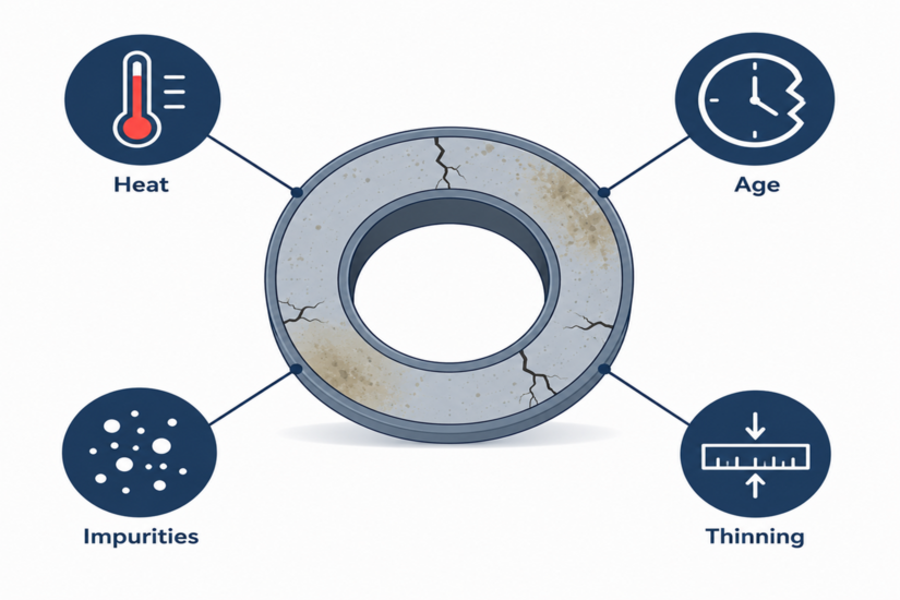
What causes dielectric breakdown in high-voltage assets?
Insulation failure rarely happens out of nowhere. It is usually the end of a slow process of degradation, sometimes years in the making. The main drivers are below.
Electrical stress and partial discharge
When the local electric field exceeds what a small region of insulation can handle, you get partial discharge: tiny sparks inside voids, cracks, or at interfaces in the insulation.
Each discharge is small. The problem is the accumulation:
- Over months and years, partial discharge erodes the material.
- It carves conductive channels called electrical trees.
- Dielectric strength drops steadily until full breakdown follows.
Partial discharge is one of the most important early indicators in HV condition monitoring.
Thermal ageing
Heat is the enemy of insulation. Every insulation system has a temperature rating, and sustained operation above it speeds up chemical breakdown of the material.
A common industry rule of thumb, drawn from the Montsinger and Arrhenius work on insulation life, is that insulation life roughly halves for every 8 to 10°C of sustained overtemperature. It is a rule of thumb rather than a fixed law, but it explains why the following matter so much:
- Overloading
- Poor ventilation
- Blocked or failed cooling
- High ambient temperatures
Moisture and contamination
Water is a serious problem for insulation. Moisture ingress lowers insulation resistance, promotes tracking across surfaces, and in cables drives water treeing, a degradation mechanism that eats away at polymer insulation over time.
Contamination such as dust, salt, oil, or carbon deposits creates conductive paths across surfaces that should be clean and dry.
Mechanical damage and ageing
Vibration, thermal cycling, installation damage and rodent activity all create the cracks, voids and weak points where breakdown starts. Common culprits include:
- A nick in cable insulation from a careless pull
- A transformer left to vibrate against its mounts
- Switchgear with cracked bushings
Transient overvoltages
Lightning strikes, switching surges and faults elsewhere on the network can briefly impose voltages far above the normal rating. A single transient can be enough to trigger breakdown in insulation that was already weakened. That is one reason surge protection and proper coordination matter.
What are the warning signs before insulation fails?
Insulation usually warns you before it lets go, if you know what to look and listen for. The signs include:
- The smell of ozone or burning around switchgear
- Audible buzzing or crackling from partial discharge
- Visible tracking marks or carbon trails on insulators
- Discoloured or brittle insulation
- Oil that has darkened or smells of overheating
- Rising temperatures picked up on thermographic surveys
None of these should be ignored. Under EAWR 1989, electrical systems must be maintained so as to prevent danger so far as is reasonably practicable. An asset showing these signs is a danger that needs assessing by a competent person.
How is the insulation condition tested?
Testing exists to catch degradation before it becomes a breakdown in service. The methods used on HV assets are different in scale from low-voltage work, but the logic is the same: measure the health of the insulation under controlled conditions rather than waiting for it to fail under load.
Insulation resistance testing
Insulation resistance (IR) testing applies a DC voltage and measures the resulting leakage current, expressed as a resistance value.
- For low-voltage installations, BS 7671 sets out test voltages and minimum insulation resistance values in its tables, with a 500V DC test applied to most circuits up to 500V nominal.
- On HV assets, higher test voltages and more specialised instruments are used.
Either way, the principle is the same: compare readings against expected minimums and against historical trends.
Partial discharge testing
Because partial discharge is an early sign of decay, dedicated PD testing, whether online or offline, lets engineers detect and locate discharge activity inside cables, transformers and switchgear long before failure. Trending PD over time is one of the most valuable tools in HV asset management.
Tan delta and polarisation index
- Tan delta (dissipation factor) testing measures how much energy the insulation wastes as heat. This rises as insulation ages and absorbs moisture.
- Polarisation index (PI) is the ratio of the 10-minute to the 1-minute insulation resistance reading. It shows whether windings are dry and healthy or damp and degraded.
Thermography and oil analysis
- Infrared thermography finds hot joints and overloaded components without contact.
- Dissolved gas analysis (DGA) and oil testing, for oil-filled plant such as transformers, reveal internal faults, moisture content and ageing that no external inspection could see.
Who is allowed to carry out this work?
HV testing and inspection are reserved for competent persons, and the bar is high.
- The HSE uses the term "competent person".
- BS 7671 uses "skilled person", defined as someone with the education, training and practical skill to perceive risk and avoid the hazards electricity creates.
For HV work specifically, that competence is backed by authorisation under a documented safety system, appropriate training, and DNO or site-specific procedures. Test instruments must be calibrated and rated for the task.
This is exactly why HV work is closed to DIY and to anyone not yet trained. A breakdown event on energised HV plant can be fatal, and the controls around the work exist for that reason.
How do you reduce the risk of dielectric breakdown?
The risk of dielectric breakdown is reduced by managing the conditions that cause it. In practice that means:
- Keeping assets within their temperature ratings
- Keeping insulation clean and dry
- Protecting against transient overvoltages
- Running a structured testing and inspection regime that trends results over time rather than relying on one-off readings
Treat insulation as a consumable that ages, not a fixed feature that lasts forever. Planned condition monitoring, prompt response to warning signs, and accurate record keeping turn insulation failure from a surprise into a managed, predictable event handled on your terms.
A solid understanding of electrical safety starts with the right foundation. Explore TradeFox to build practical skills through interactive learning and strengthen your knowledge before taking on more advanced electrical work.
Working safely with HV insulation
Dielectric breakdown is the mechanism behind most HV insulation failures, and almost all of it is preventable with the right knowledge, testing and response.
If you are training toward HV work, build your understanding of insulation behaviour early, get properly qualified, and never treat a warning sign as background noise. If you are responsible for HV assets and you are seeing any of the symptoms covered here, get a competent person to assess them before the asset fails on its own terms.
For the underlying standards and duties, consult the relevant UK regulatory sources linked below and your own organisation’s safety rules.