Earth bonding is one of those topics that sounds straightforward on paper and then catches half the trade out when it comes to inspection day. Inspectors fail installations every week over it. Not because the work is hard, but because the rules are misunderstood, the testing is skipped, or someone bonded a sink that never needed bonding while leaving the gas service sitting un-clamped six feet from the meter.
This guide walks through the distinction between main protective bonding and supplementary bonding under BS 7671, what an inspector looks for first in a domestic property, and the small details that turn a satisfactory EICR into an unsatisfactory one.
Earthing vs Earth Bonding: Get The Terms Right
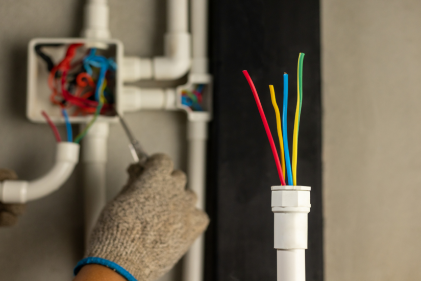
Before anything else, the language matters. Earthing and bonding use the same green and yellow conductors, but they do entirely different jobs.
Earthing connects exposed-conductive-parts (the metalwork of the electrical installation itself, such as metal enclosures, back boxes, and the consumer unit casing) to the Main Earthing Terminal (MET) so that a fault current has a path back to source. That path is what allows the protective device to operate.
Earth bonding connects extraneous-conductive-parts (metal that is not part of the electrical installation but could introduce a potential into the building, typically incoming metallic gas and water pipes) to the same MET. The aim is to keep everything at the same potential during a fault, so a person touching two metal parts at once does not become the path between them.
Le IET defines an extraneous-conductive-part as “a conductive part liable to introduce a potential, generally Earth potential, and not forming part of the electrical installation.” All three conditions have to be met. That definition is the source of more EICR disagreements than almost any other point in the regs.
Main Protective Bonding: What BS 7671 Requires
Main protective bonding is the non-negotiable part. Regulation 411.3.1.2 requires main protective bonding conductors to connect any extraneous-conductive-parts to the MET. In a typical UK domestic property, that means the incoming metallic gas pipe and the incoming metallic water pipe, plus any other service that introduces earth potential into the building (oil lines and structural steelwork can apply in some cases).
Location Of The Bond
Regulation 544.1.2 sets the location rule. The connection should be made as near as practicable to the point of entry, normally within 600mm of the meter outlet, on the consumer side, and before any branch or tee in the pipework. The exact wording in BS 7671 uses “where practicable,” which matters. If the meter cupboard geometry genuinely prevents a connection within 600mm, the closest practicable accessible point before the first branch is acceptable. The same 600mm guidance is mirrored in BS 6891:2015 clause 8.4.3.2 for gas installation pipework, and in Gas Safe Register Technical Bulletin 102, which also recognises an external meter box termination as an acceptable alternative.
What this means in practice:
- Consumer side of the meter, not the inlet.
- Before the first tee or branch.
- On hard metal pipework, not on a flexible connector.
- Accessible for future inspection. Boxed-in or buried bonds will be flagged.
Conductor Size
Regulation 544.1.1 governs sizing, and the rule splits by supply type.
A 6mm² bond on a PME installation will be coded. Do not undersize.
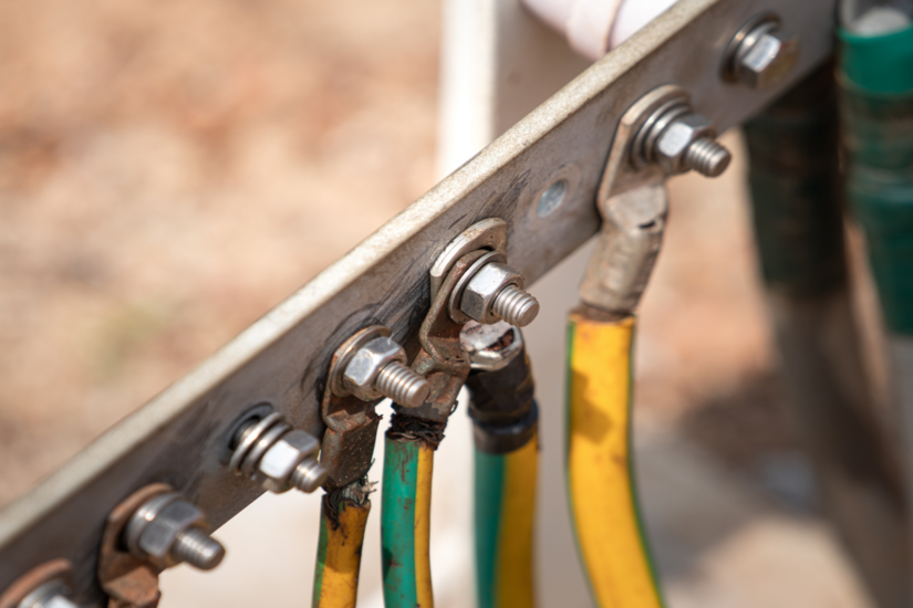
Clamp Standard
- Use a BS 951 earth clamp.
- Fix to clean, bare metal. Paint, dirt, and corrosion all kill the connection.
- Fit the "Safety Electrical Connection - Do Not Remove" label.
- Keep it accessible.
Continuity Test Values
BS 7671 does not set a maximum resistance for the main protective bonding conductor itself. What inspectors look for is a satisfactory continuity reading that reflects the length and CSA of the conductor. The often-quoted 0.05Ω figure relates to the joint at the clamp, taken from IET Guidance Note 3, and is the expected difference between the second test measurement (to the pipe) and the first measurement (to the clamp). It is not a hard limit on the overall conductor resistance, and the regulation does not impose one.
Plastic Pipework: When Earth Bonding Is Not Required
This is where a lot of well-meaning work goes wrong. If the incoming gas or water service is plastic, the metallic pipework inside the property is not an extraneous-conductive-part. It cannot introduce earth potential from outside. Bonding it is not required and, in some cases, can actually create problems by exporting fault current along internal pipework.
The same logic applies to:
- Internal plumbing fed by a plastic rising main.
- Stainless steel kitchen furniture.
- Bathroom radiators on plastic pipe.
None of these are extraneous-conductive-parts by the BS 7671 definition. Bonding them is a habit, not a requirement.
Where visual inspection cannot confirm what feeds a metallic part, a resistance measurement to the MET will settle it. The threshold derived from the formula in IET Guidance Note 8 determines whether the part introduces earth potential. If the measured resistance is above that threshold, the part is not extraneous and does not need bonding.
Supplementary Bonding: The Bathroom Question
Supplementary bonding sits inside the special location rules in Section 701 of BS 7671. In older domestic installations, you would expect to see green and yellow conductors linking the bath, taps, radiator, and any other metal in the room together. In a modern installation, supplementary bonding can often be omitted, but only if every condition in Regulation 701.415.2 is met.
The Three Conditions For Omission
- All final circuits in the location comply with the automatic disconnection times in Regulation 411.3.2.
- All final circuits have additional protection by a 30mA RCD.
- All extraneous-conductive-parts in the location are effectively connected to the main protective bonding (i.e. main protective bonding to the incoming services has been correctly carried out).
If any one condition fails, supplementary bonding has to be installed. That last point catches people out. If the main bonding is undersized, missing, or on the wrong side of the meter, the bathroom cannot rely on the omission.
Sizing And Testing
Supplementary bonding conductors are sized under Regulation 544.2. The practical minimum for most domestic work is 2.5mm² copper with mechanical protection, or 4mm² copper without. The test criterion is set in Regulation 415.2.2:
R ≤ 50/Ia
Where R is the resistance between simultaneously accessible parts, 50 is the maximum acceptable touch voltage in volts, and Ia is the operating current of the protective device within the required disconnection time.
For a 30mA RCD, that gives R ≤ 1,667Ω. For a 6A Type B MCB requiring 30A to operate within 5 seconds, R ≤ 1.67Ω. The figure depends entirely on what protects the circuit.
Where Inspectors Look First During An EICR
Walk into an EICR with an experienced inspector and you will see the same pattern every time. They head for the meter cupboard before they touch the consumer unit. Here is the running order, and why.
1. Gas Meter
The inspector checks for a correctly sized conductor (typically 10mm² on a domestic PME service) terminated on a BS 951 clamp, on the consumer side, within 600mm of the outlet where practicable, on clean metal, with the warning label fitted.
Missing or inadequate main protective bonding on the gas service is one of the most consistently observed EICR failures across the UK private rented sector. It almost always attracts a C2 code (potentially dangerous, requiring urgent remedial work within 28 days).
2. Water Main
Same checks at the stop-tap. The bond goes on the metallic incoming pipe within 600mm of the point of entry where practicable, before the first branch. Where the supply is plastic up to the stop-tap and then converts to copper, the inspector assesses whether the metal portion actually introduces earth potential. Usually it does not.
3. Main Earthing Terminal
They will lift the MET cover and check:
- Bonding conductors actually terminate at the MET.
- The earthing conductor is correctly sized for the supply type.
- The MET is identifiable and labelled.
- Terminations are tight and free of corrosion.
Loose terminations, mixed conductor sizes, and undersized earthing conductors on PME supplies are common observations.
4. Supply Type Identification
TN-S, TN-C-S (PME), or TT. The supply type drives the bonding conductor size and dictates whether an earth electrode is needed. Getting the supply type wrong on the certificate is itself a quality issue. Amendment 3:2024 to BS 7671 now recommends an additional earth electrode for all TN systems under Regulation 411.4.2.
5. Bathrooms
If the installation pre-dates RCD protection or fails the conditions in 701.415.2, the inspector looks for supplementary bonding to the bath, taps, towel rail, and any radiator that meets the extraneous-conductive-part definition. Older installations frequently have it. Modern compliant installations often legitimately omit it.
6. Outbuildings, Sheds, Garages
Any sub-installation fed from the main building needs its own assessment. TT supplies often appear here, especially on outbuildings where PME has not been extended.
Common EICR Failures Worth Knowing
A short list of the failures that come up week after week:
- Main protective bonding conductor terminated outside the practicable 600mm window. Very common in retrofitted gas meters where the meter has been moved but the bond was left in place.
- 6mm² bonding conductor on a PME installation where 10mm² or larger is required.
- Clamp fitted to a painted or chromed pipe with no preparation, giving a high-resistance connection.
- Missing BS 951 warning label.
- Bonding conductor disconnected at the MET because someone "tidied up" the cupboard.
- Bonding installed to plastic-fed internal pipework that does not require it, while the actual incoming metallic service goes unbonded.
- Supplementary bonding omitted in a bathroom that does not satisfy 701.415.2 because the consumer unit has no 30mA RCD coverage on the relevant circuits.
- Internal gas pipework altered during a boiler replacement or kitchen refit, leaving the bond on a section now isolated from the meter by a plastic insert.
Code allocation is the inspector’s call, but missing main bonding will almost always be C2 under current NICEIC guidance and the Electrical Safety First Best Practice Guide 4. For landlords under the Electrical Safety Standards in the Private Rented Sector (England) Regulations 2020, a C2 means an unsatisfactory report, 28 days to remediate, and potential local authority penalties of up to £30,000 if ignored.
PME And The Open-PEN Risk
One safety point worth stressing for trades new to this work. Under TN-C-S (PME) supplies, a broken supply neutral in the street can elevate all bonded metalwork inside the property towards live potential, because the building’s bonded mass becomes the alternative return path for neutral current.
This is the reason PME installations require larger bonding conductors than TN-S systems (Table 54.8), and the reason loose, corroded, or undersized terminations are taken so seriously by inspectors. A bond that looks fine until a network fault occurs is not fine. Mechanical integrity of every clamp, lug, and terminal in the bonding system is the difference between a controlled fault and an exported potential.
Testing The Bonding: Good Practice
Continuity testing of the main protective bonding is a long-lead test with the conductor disconnected from the MET. The expected reading is the resistance per metre of the conductor multiplied by the run length, plus a small allowance for the clamp joint.
For 10mm² copper at 20°C, the resistance is approximately 1.83mΩ per metre. A 5-metre run should read around 9–10mΩ at the conductor, plus the clamp contribution. If the reading is significantly higher than that calculation, something is wrong:
- Poor clamp connection.
- Corrosion at a termination.
- Damaged conductor.
- Joint that was never tightened properly.
For supplementary bonding, the test is between simultaneously accessible parts and the protective conductor of the circuit. The result must satisfy R ≤ 50/Ia for the relevant protective device.
Tradesmen new to this work should sit with a copy of IET Guidance Note 3 (Inspection and Testing) on the bench and learn the procedure before they certify anything.
Reconnect the conductor to the MET after every test. Forgetting that step is how installations leave site in a worse condition than they arrived.
Why The Rules Exist
Earth bonding is not paperwork. It is the single feature that prevents a person standing in a bathroom from becoming the conducting path between a faulty appliance and a metal pipe at earth potential.
The 600mm guidance exists because the closer the bond sits to the point where the service enters the building, the more effective the equipotential zone. A bond placed three metres downstream leaves a length of incoming metal pipe outside the zone, which is exactly what the regulation is trying to avoid. Accessibility for inspection is a useful side benefit, not the primary reason.
The conductor sizes are derived from fault current calculations under PME conditions, where a broken supply neutral can throw bonded metalwork up towards live potential. The whole framework is engineered for the worst-case fault, not for ordinary operation.
Keep your bonding checks sharp and your testing routine consistent. TradeFox helps you build practical skills that carry into real jobs, with clear training you can work through at your own pace.
Keeping Current With The Regulations
For tradesmen building their knowledge, the most useful documents outside BS 7671 itself are:
- IET On-Site Guide for quick reference on standard domestic work.
- IET Guidance Note 3 for inspection and testing procedure.
- IET Guidance Note 8 for the detail on earthing and bonding, including the test method for determining whether a part is extraneous.
- NICEIC and NAPIT technical bulletins, which regularly clarify the trickier corners of 544.1.1 and 701.415.2.
- Electrical Safety First Best Practice Guide 4 for EICR coding.
The regulations evolve. Amendment 3 (2024) brought changes to TN earth electrode recommendations, and Amendment 4 (currently in draft for 2026) introduces a new Section 545 on functional earthing for ICT and renewable installations. The difference between a satisfactory EICR and an unsatisfactory one is often whether the person doing the work has kept current with the wording of 411.3.1.2, 544.1.2, and 701.415.2. Bonding done properly is invisible. That is the point.