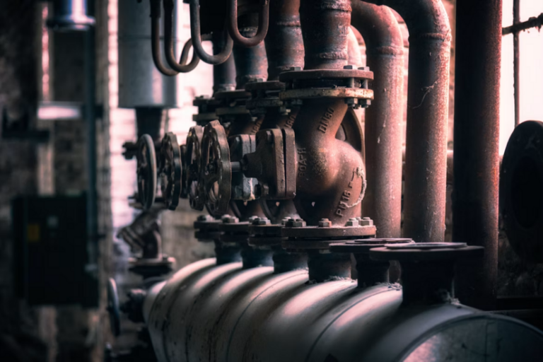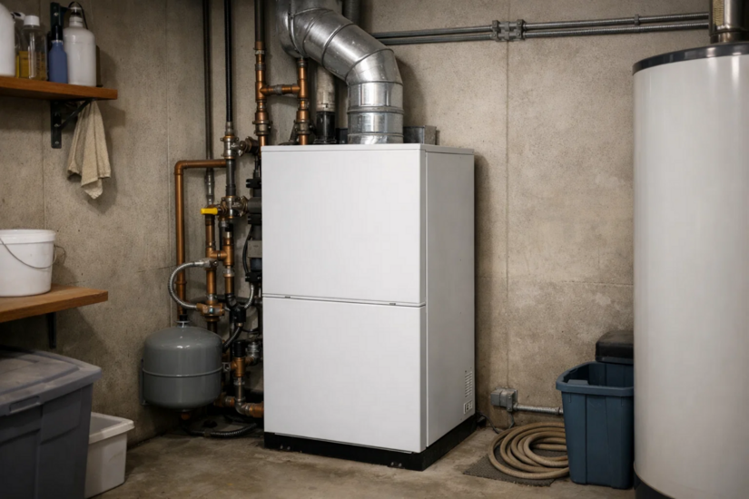
Navigating the complexities of legacy heating systems remains a core requirement for gas engineers across the United Kingdom. While modern condensing boilers utilise electronic ignition sequences, a significant number of older appliances relying on standing pilots are still operational. For apprentices and seasoned tradesmen alike, diagnosing pilot light problems efficiently and safely is a fundamental skill.
This comprehensive technical guide details the mechanical and environmental failures associated with standing pilots. It outlines the precise diagnostic checks required and defines the strict regulatory boundaries dictating when an appliance must be isolated.
The Regulatory Framework and Professional Competence
Before inspecting any gas appliance, the foundational rule of the UK plumbing and heating trade applies. Only individuals registered with the Gas Safe Register are legally permitted to undertake work on gas fittings. This is mandated by the Gas Safety (Installation and Use) Regulations 1998.
Diagnosing pilot light problems is not a task for the general public. It involves breaking into the gas line, measuring combustion characteristics, and making definitive judgments on appliance safety. Professionals must approach these systems with a comprehensive understanding of the Gas Industry Unsafe Situations Procedure (GIUSP) to protect themselves and the end user.
The Mechanics of a Standing Pilot System
To troubleshoot effectively, an engineer must fully understand the electromechanical relationship between the pilot burner, the thermocouple, and the gas valve.
The pilot light serves a dual purpose. It acts as the ignition source for the main burner and powers the primary safety device, the thermocouple. The thermocouple contains two dissimilar metals joined at the tip. When the pilot flame heats this junction, it generates a small direct current. This continuous electrical current travels down the copper lead to an electromagnetic coil situated inside the main gas valve.
As long as the millivoltage is sufficient, the electromagnet holds the pilot gas valve open. If the pilot flame extinguishes, the thermocouple cools down, the voltage drops to zero, and the spring-loaded safety valve snaps shut. This prevents unburnt gas from freely escaping into the property.
Common Causes of Pilot Light Problems
When an end user reports that their boiler or water heater keeps locking out, the fault usually lies within one of four specific areas.
Thermocouple Degradation and Failure
The thermocouple is subjected to constant thermal stress. Over years of continuous operation, the copper casing can degrade, or carbon deposits can insulate the tip. This prevents the transfer of heat required to generate the necessary millivoltage. Furthermore, the internal wires can break, causing an open circuit.
Another common issue is incorrect positioning. The tip of the thermocouple must be enveloped by the upper third of the pilot flame. If the flame is deflecting away due to draughts or partial blockages, the thermocouple will not reach the necessary operating temperature.
Blocked or Partially Obstructed Pilot Injectors
The pilot injector contains a microscopic orifice designed to allow a very specific volume of gas to pass through. Due to its size, it is highly susceptible to blockages from household dust, lint, and spider webs.
A partially blocked injector will produce a weak, yellow, and wavy flame instead of a sharp, blue cone. This weak flame is often insufficient to heat the thermocouple correctly. Additionally, a yellow flame indicates incomplete combustion, which can lead to the dangerous production of carbon monoxide and excessive soot buildup.
Gas Supply and Valve Solenoid Faults
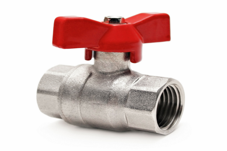
If the pilot will not light at all, the engineer must verify the presence of gas. This involves checking that the emergency control valve is open and that the meter is functioning. However, if gas is present at the appliance isolation valve but not at the pilot burner, the internal passageways of the gas valve may be blocked.
Alternatively, the internal electromagnet may have failed. While the thermocouple might be generating the correct voltage, a faulty solenoid coil within the valve will fail to hold the safety mechanism open once the manual override button is released.
Environmental Factors, Draughts, and Vitiated Air
External environmental conditions frequently cause standing pilot failures. A poorly sealed boiler casing or an excessively strong draught from a damaged flue can physically blow the flame out.
Equally critical is the quality of the combustion air. If an appliance is situated in a confined space without adequate ventilation as prescribed by Building Regulations Document J, it may consume the available oxygen. This results in a vitiated atmosphere. The pilot flame will become unstable, lift away from the burner, and eventually extinguish as it struggles to draw in sufficient oxygen.
Professional Diagnostic Procedures and Safe Checks
When arriving on site, a structured, methodical approach is required. Engineers must ensure all diagnostic equipment, specifically multimeters and flue gas analysers, hold valid, in-date calibration certificates to ensure tests are legally defensible.
Visual Inspection, Gas Tightness, and Flame Analysis
Initiate the service call with a thorough visual inspection of the appliance casing. Look for signs of scorching, soot, or heat damage. Crucially, before introducing any ignition source to diagnose a fault, an engineer must unequivocally confirm there is no unburnt gas in the vicinity. Standard industry practice dictates performing a let-by and tightness test at the meter to verify the integrity of the gas installation.
Once confirmed safe, attempt to light the pilot manually. Observe the flame characteristics. A healthy pilot flame should be crisp, blue, and strike the thermocouple directly. If the flame is yellow or lifting, this immediately indicates issues with the primary air supply, an obstructed injector, or a compromised flue system.
Millivolt Testing the Thermocouple
Instead of indiscriminately replacing parts, tradesmen must use a calibrated multimeter to test the component objectively.
- Isolate the gas supply.
- Disconnect the thermocouple from the gas valve to perform an open-circuit test.
- Set the digital multimeter to read direct current millivolts.
- Place one probe on the copper lead and the other on the tip contact.
- Using a secondary heat source, heat the tip of the thermocouple.
A healthy thermocouple on an open-circuit test will quickly climb to between 20mV and 30mV. Testing the thermocouple under load, known as a closed-circuit test, will yield a much lower reading, typically between 10mV and 15mV. If the reading is sluggish, erratic, or fails to reach these minimums, the component is defective and requires replacement.

Injector Cleaning Protocols
If the injector is suspected to be the root cause of the issue, it must be removed and cleaned strictly according to the manufacturer instructions.
Professionals must never use wire, needles, drill bits, or cleaning pins to clear a pilot orifice. Introducing any physical object will scratch or enlarge the precise brass opening. Enlarging the orifice alters the gas to air ratio, resulting in a highly dangerous combustion profile. The guidance is strictly limited to using compressed air or soaking the injector in an appropriate solvent. If the blockage cannot be safely removed using these methods, the injector must be replaced entirely.
Troubleshooting Matrix
| Symptom | Likely Cause | Recommended Action |
|---|---|---|
| Pilot goes out immediately after releasing override. | Faulty thermocouple or valve solenoid. | Perform open and closed-circuit millivolt tests. |
| Weak, yellow, or wavy pilot flame. | Blocked injector or restricted primary air. | Remove and clean injector with compressed air. |
| Pilot flame lifts away from burner. | Vitiated air or excessive draught. | Check room ventilation and perform flue integrity checks. |
| No gas at pilot burner. | Blocked gas valve or isolated supply. | Verify gas at meter and test valve continuity. |
When to Stop: Safety Protocols and Classifications
The most critical skill a tradesman possesses is knowing exactly when to stop attempting a repair. Addressing pilot light problems can often reveal far more severe underlying faults. Under the Gas Industry Unsafe Situations Procedure, an engineer is obligated to assess the risk an appliance poses and classify it accordingly.
"At Risk" (AR) Situations
If you discover a fault that could potentially become a danger to life or property, the appliance is classified as “At Risk” (AR). An example would be an appliance lacking the required ventilation but currently passing a flue gas analysis. In this scenario, the engineer must turn off the appliance, issue a Warning Notice, and advise the responsible person not to use it until the fault is rectified.
"Immediately Dangerous" (ID) Situations
If an inspection reveals a fault that poses an immediate threat to life, the appliance is classified as “Immediately Dangerous” (ID). Examples include a cracked heat exchanger, a completely blocked flue, or significant carbon monoxide spillage.
In ID situations, the engineer must act decisively.
- Immediately disconnect the appliance from the gas supply.
- Cap off the pipework securely.
- Attach a prominent "Danger Do Not Use" label to the appliance.
- Issue a formal Warning Notice to the homeowner or landlord.
If the customer refuses permission to disconnect a fundamentally unsafe appliance, the engineer must follow strict legal procedures. Under the GIUSP, contacting the Emergency Service Provider (ESP) is a mandatory requirement. The ESP possesses the legal powers of entry and disconnection for natural gas supplies, which standard Gas Safe engineers do not have. Safety is non-negotiable.
If you want to understand the basics before you book a visit, TradeFox offers a guide to help you spot common warning signs, describe problems clearly, and know when to stop.
Conclusion
Mastering the diagnosis of standing pilot faults is essential for any competent heating engineer operating in the UK. By understanding the mechanical principles, recognising the signs of vitiated air, and conducting accurate multimeter testing, tradesmen can resolve call-outs efficiently. However, the overarching priority remains strict adherence to the Gas Safe regulations and the GIUSP. Diagnosing a simple fault is routine work, but identifying the subtle signs of a dangerous combustion environment is what defines a true industry professional.