Electrical installations must deliver power safely and efficiently from the origin of the supply to the final piece of connected equipment. One of the most critical factors in achieving this is managing the electrical pressure lost along the length of a circuit. This phenomenon is universally known in the trade as Voltage Drop. When cables are undersized or run over excessive distances, the resistance within the copper conductors consumes a portion of the supply voltage before it ever reaches the intended load.
For professional electricians and dedicated apprentices, understanding this concept is not optional. It is a fundamental requirement of the BS 7671:2018+A4:2026 Requirements for Electrical Installations. Ignoring this principle during the design or installation phase leads to underperforming appliances, potential fire hazards, and outright non compliance with UK law. This guide breaks down the physical symptoms encountered on domestic sites, the strict regulatory limits, and the exact methods competent tradesmen use to calculate and verify safe limits.
The Core Physics of Cable Resistance
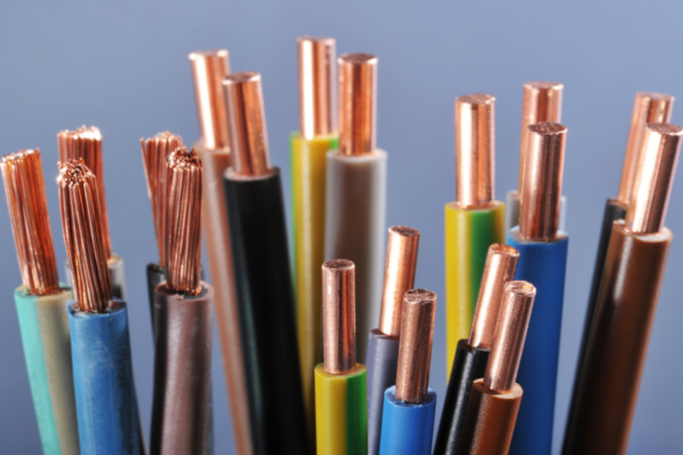
Every conductive material presents a certain level of resistance to the flow of alternating current. In domestic wiring, this involves copper conductors. As the length of a cable increases, the total resistance of that circuit also increases proportionally. When an electrical current flows through this resistance, a certain amount of energy is dissipated as heat.
This dissipation results in a lower voltage at the load end of the circuit compared to the supply end. The heavier the current drawn by the appliance, the more pronounced the drop in electrical pressure becomes. A lighting circuit drawing one amp might perform perfectly over a fifty metre run. Conversely, an induction hob drawing thirty amps over the exact same distance and cable size would suffer a catastrophic loss of electrical pressure.
Recognising the Symptoms on Site
Homeowners rarely understand the technicalities of electrical impedance. They usually call an electrician when they notice bizarre or frustrating behaviour from their household systems. Recognising these physical symptoms is the first step in diagnosing a poorly designed circuit.
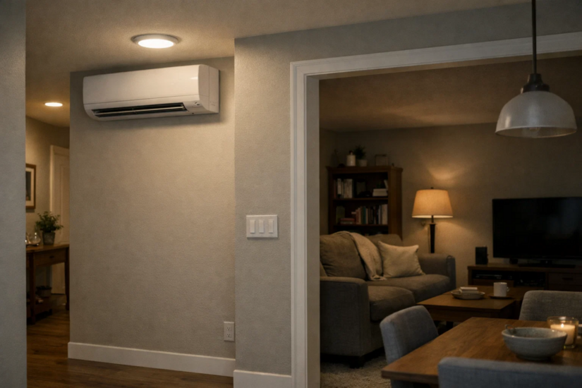
Dimming and Flickering Lighting
The most common and visually obvious symptom is lighting instability. If a homeowner reports that their living room lights dim significantly when the washing machine enters a spin cycle or when an electric shower is turned on, the installation is suffering from a lack of adequate voltage. Incandescent and halogen bulbs physically dim, while modern LED drivers may struggle to regulate the current, leading to a noticeable strobing or flickering effect.
Motor Strain and Premature Failure
Appliances that rely on electric motors are highly sensitive to supply fluctuations. Refrigerators, washing machines, and extractor fans require a specific voltage to generate the necessary torque to spin. When the voltage is too low, the motor pulls additional current to compensate and attempt to perform the same amount of mechanical work. This excessive current generates immense heat, degrading the motor windings over time and leading to premature, expensive failures.
Erratic Electronic Equipment

Modern domestic properties are filled with sensitive microprocessors. Smart home hubs, high end televisions, and computer systems rely on stable power supplies. Severe fluctuations can cause these devices to randomly reset, fail to boot correctly, or suffer permanent damage to their internal power supply units.
The True Cost of Poor Design
Designing a circuit properly is about much more than just keeping the lights bright. The implications of getting the calculations wrong are severe.
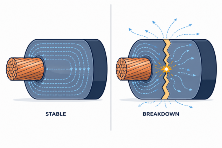
Overheating and Fire Risks
The energy lost along an undersized cable does not simply vanish. It converts directly into heat energy within the copper conductors and the surrounding PVC insulation. Continuous heavy loads on a circuit with excessive resistance will cause the thermoplastic insulation to degrade, become brittle, and eventually melt. This creates a severe risk of arcing, short circuits, and electrical fires hidden within floor voids or stud walls.
Financial and Energy Inefficiency
Cables acting as unintended heating elements represent pure energy waste. The homeowner pays the utility company for power that is literally warming the inside of their walls rather than boiling their kettle or running their television. Over the lifespan of a property, this inefficiency compounds into a significant financial loss.
BS 7671 Requirements and Strict Legal Limits
The UK wiring regulations provide absolute clarity on acceptable limits. Appendix 4 of the 18th Edition of BS 7671 dictates that the Voltage Drop between the origin of the installation and any load point must not exceed specific percentage values of the nominal supply voltage. For a standard single phase 230 volt domestic supply directly from a public low voltage distribution network, the limits are strictly defined.
- Lighting circuits must not exceed a 3 percent drop, which equates to a maximum allowable drop of 6.9 volts.
- Power circuits must not exceed a 5 percent drop, which equates to a maximum allowable drop of 11.5 volts.
These limits ensure that all connected equipment operates within the safe voltage tolerances specified by the original equipment manufacturers.
How Professional Electricians Calculate and Check
Tradesmen do not rely on guesswork when sizing cables for a new extension, an outbuilding, or a heavy radial circuit like an electric vehicle charge point. They use specific mathematical formulas and professional testing equipment.
The Design Stage Calculation
Before a single floorboard is lifted, the design must be mathematically sound. Electricians use the standard formula found in BS 7671 Appendix 4. The formula requires the millivolt drop per ampere per metre value of the chosen cable, the design current of the circuit, and the total length of the run.
The calculation is standard practice. You multiply the tabulated millivolt value by the design current in amps, multiply that result by the length of the circuit in metres, and then divide the entire figure by one thousand to convert the result from millivolts back into volts. For example, a standard 2.5 millimetre squared Twin and Earth cable has a tabulated drop of 18 millivolts per amp per metre. If the final calculated number exceeds the 6.9 volt or 11.5 volt limits mentioned earlier, the cable cross sectional area must be increased.
On-Site Verification with a Multi Function Tester
Once the installation is physically complete, the design must be verified through dead and live testing. An electrician will use a calibrated multi function tester to perform these checks. While a direct voltage reading under maximum load is sometimes impractical, electricians rely on measuring the actual impedance of the circuit.
The most precise method is measuring the R1 + RN value, which is the combined resistance of the Line and Neutral conductors, during the dead testing phase. By measuring this R1 + RN resistance, the tradesman establishes the actual physical resistance of the installed copper path specifically responsible for carrying the load. If the measured resistance values are significantly higher than the calculated design values, the electrician knows there is a hidden issue. This could be a loose terminal connection, a damaged conductor, or a cable run that is much longer than originally planned.
Remediation and Cable Sizing Strategies
When an existing circuit fails these checks, or when a proposed design exceeds the legal limits, professional mitigation strategies must be applied. The most common and effective solution is simply increasing the cross sectional area of the live conductors. Upgrading a radial power circuit from a 2.5 millimetre squared cable to a 4.0 millimetre squared cable significantly reduces the internal resistance, allowing the voltage to travel further without degrading.
A controversial strategy used in UK domestic wiring is the ring final circuit. By forming a continuous loop of cable that starts and ends at the same protective device, the current is divided down two parallel paths. This effectively halves the resistance and doubles the current carrying capacity for a given cable size, vastly improving the voltage stability across the entire floor plan.
If you’re learning what voltage drop looks like in real homes, Tradefox electrical simulations help you spot patterns and talk to electricians with confidence, without ever touching live circuits.
Maintaining Standards in Domestic Wiring
Ensuring the correct electrical pressure reaches every socket and luminaire is a hallmark of a competent tradesman. Proper cable sizing prevents appliance damage, eliminates hidden fire risks, and ensures total compliance with the latest BS 7671:2018+A4:2026 wiring regulations.
Managing Voltage Drop effectively is what separates a professional installation from a dangerous liability. Professional electricians protect their customers and their own livelihoods by executing precise calculations and rigorous testing on every single project.