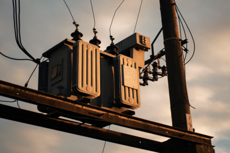


The vacuum circuit breaker has become the workhorse of medium-voltage distribution across the UK. You will find it in grid substations, industrial switchrooms, rail traction supplies and large commercial developments. If you work on or near HV switchgear, understanding how these devices interrupt fault current, how their mechanisms behave, and where the real hazards sit during maintenance is not optional knowledge. It is the difference between a controlled job and a serious injury.
This guide is written for working tradesmen and those training toward HV authorisation. It is not a substitute for site-specific procedures, manufacturer instructions, or formal competency assessment.
How Arc Interruption Works in a Vacuum
Every circuit breaker faces the same problem. When the contacts separate under load or fault conditions, current is still flowing, and that separation draws an arc. In an oil or SF6 breaker, a medium cools and de-ionises the gap to quench that arc. Vacuum switchgear does something cleverer. It relies on the near-total absence of a medium.
Inside a sealed vacuum interrupter, pressure is held extremely low, typically well below 10⁻⁴ bar. With almost no gas molecules present, there is very little to ionise and sustain an arc. When the contacts part, the arc that forms is a metal vapour arc, drawn from the contact surface itself rather than from any surrounding gas.
That vapour arc burns until the alternating current reaches its natural zero crossing. On a UK 50 Hz system, a current zero occurs every 10 milliseconds. At that point two things happen in quick succession:
- The metal vapour condenses back onto the contacts almost instantly.
- Dielectric strength across the gap recovers within microseconds, far faster than in most other interrupting media.
It is worth being precise here. The breaker interrupts the current at the next natural zero, which may be up to 10 milliseconds away. The rapid microsecond recovery describes how quickly the gap regains its insulating strength after that zero, not the interruption time itself. This fast recovery is why the device copes so well with the transient recovery voltage that appears across the contacts immediately after interruption.
Contact Design and the Magnetic Field
Two contact features make this reliable, and both are about controlling where the arc sits.
- Radial magnetic field contacts drive the arc around the contact face so it never dwells in one spot. This keeps erosion low.
- Axial magnetic field contacts keep the arc diffuse and spread evenly across the surface. This matters most at high short-circuit levels.
Either approach protects the contact surface, which is what allows a vacuum circuit breaker to hold its rated performance across a long operating life.
Operating Mechanisms: Storing and Releasing Energy
Interrupting current is only half the job. The mechanism has to move the contacts fast enough, and with enough force, to open under fault conditions and to close onto a potential fault without welding shut.
Spring-Operated Mechanisms
Most modern medium-voltage units use a spring-operated mechanism. A motor charges a closing spring, storing mechanical energy. On a close command, that energy releases in milliseconds to drive the contacts together and, at the same time, charge the opening spring. The trip spring then sits ready, so the breaker can open instantly on a protection signal even if the control supply is lost. This stored-energy principle is what allows an auto-reclose duty, a sequence set out in the current edition of the governing standard.
Magnetic Actuator Mechanisms
Magnetic actuator designs are increasingly common. Instead of a spring stack, a permanent magnet holds the contacts in position and a coil drives them between states. Fewer moving parts means fewer wear points. The trade-off is that maintenance attention shifts toward the electronics and capacitor banks that drive the actuator.
Whatever the design, the same warning applies. The mechanism stores significant mechanical energy. A charged spring or a charged actuator capacitor can operate the breaker whether or not you are ready for it. Treat a charged mechanism as a live hazard in its own right.
The Standards That Govern the Kit
In the UK, medium and high-voltage AC circuit breakers are covered by BS EN IEC 62271-100, the British implementation of the international standard for high-voltage switchgear and controlgear. It applies to AC circuit breakers on systems above 1000 V and sets out the type tests, routine tests and rated values. These cover dielectric performance, temperature rise, short-circuit making and breaking, and mechanical endurance. The wider BS EN IEC 62271 series, and the common specification in Part 1, sit alongside it.
Compliance with these standards is a manufacturing and type-approval matter. Your legal duties on site come from elsewhere.
Maintenance Risks and Legal Duties
This is where people get hurt, and where the law is unambiguous.
All work on or near electrical equipment in Great Britain falls under the Electricity at Work Regulations 1989 (EAWR), made under the Health and Safety at Work etc. Act 1974 and enforced by the HSE. The regulations that matter most to this work are:
- Regulation 12 covers isolation, meaning secure disconnection and separation from every source of energy.
- Regulation 13 covers precautions for work on equipment made dead.
- Regulation 14 restricts work on or near live conductors to narrow, justified circumstances.
- Regulation 16 requires that anyone doing the work is competent for it.
Under Regulation 14, live work is only permitted where all three conditions are met: it is unreasonable for the conductor to be dead, it is reasonable to work on or near it live, and suitable precautions are taken. For routine maintenance, that bar is rarely cleared. Working dead is the default.
HSE has prosecuted where these duties were ignored. In one documented case, a contractor was injured inspecting 11,000 V switchgear that had not been isolated, and the site occupier was fined after further untrained staff worked near the exposed live equipment. The lesson is blunt. Authorisation to be on site is not the same as safe isolation.

Hazards Specific to Vacuum Switchgear
Several risks are specific to this equipment and deserve naming.
- Stored mechanical energy. Discharge the closing and opening springs, or the actuator capacitors, before any mechanical work. Confirm the mechanism state from the local indicators.
- Vacuum integrity. The ability to break current depends entirely on the vacuum holding. A cracked or leaking interrupter can look perfect yet fail to interrupt. Vacuum integrity testing, carried out to the manufacturer's method, is the only reliable check. Never judge a bottle sound from visual inspection alone.
- X-ray emission during testing. Applying high voltage across an open interrupter can generate X-rays. Manufacturers specify maximum test voltages and clearances precisely for this reason. Stay within them.
- Racking operations. Racking a truck-type breaker in or out of its cubicle puts you close to the busbar spouts. Remote racking, correct interlock sequencing, and standing clear are all part of safe practice.
- Arc flash. Even healthy switchgear carries substantial fault energy. Arc flash risk assessment, correct PPE, and a permit-to-work system for higher-risk activities are expected controls, in line with HSE guidance HSG85 and HSG230.
- End-of-life handling. A damaged or life-expired interrupter should be disposed of per manufacturer guidance and never opened. A suspected loss of vacuum combined with applied voltage is exactly the X-ray and interruption-failure scenario to avoid.
Build safer electrical habits with TradeFox by practising isolation steps, recognising hazards and reviewing key procedures through guided simulations that you can repeat at your own pace before applying them under proper supervision on site.
Where the Vacuum Circuit Breaker Fits
Compared with SF6 units, this technology uses no fluorinated greenhouse gas, which matters increasingly under UK and EU F-gas pressure. It offers long contact life, minimal maintenance of the interrupter itself, and reliable performance across medium voltage.
Its historic limit was voltage, but that ceiling has been rising. Vacuum interrupters are now produced and deployed well beyond the traditional medium-voltage band, with commercial single-break units available up to 145 kV and clean-air insulated designs entering transmission-level service. SF6 and hybrid designs still dominate the very highest voltages, but the gap is closing.
For the tradesman the takeaway is straightforward. The technology is mature and dependable, but its safety depends on respecting stored energy, verifying vacuum integrity, and never treating switchgear as safe until it has been properly isolated and proven dead under a recognised safe system of work.