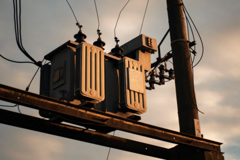
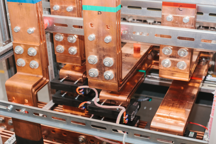
If you have ever opened a commercial distribution board, looked inside a packaged substation, or pulled the cover off an industrial panel, you have seen them. Flat, rectangular metal bars carrying current between incoming supplies, protective devices and outgoing circuits. That conductor is a busbar, and getting the specification right is the difference between a panel that runs cool for thirty years and one that fails the first time a fault drops across it.
This guide is written for working electricians, panel builders and apprentices coming up through the trade. It covers what a busbar is, the materials used, how current ratings are derived, and why short-circuit withstand is the specification you cannot afford to skim past.
What is a Busbar?
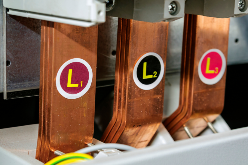
A busbar is a rigid conductor, normally bare or insulated copper or aluminium, used to distribute power within an assembly. Common examples include:
- Low-voltage main switchboards
- Motor control centres (MCCs)
- Final distribution boards
- Busbar trunking systems for lighting and rising mains
- DC conductors in EV charging hubs and battery storage systems
Earthing and bonding conductors form their own category. The main earthing terminal (MET) is defined in BS 7671 Chapter 54, and Equipotential Bonding Busbars (EBBs) are required for Group 1 and Group 2 medical locations under Section 710, which received a major revision in BS 7671:2018+A4:2026 (published 15 April 2026).
The Governing Standards
The governing product standard for low-voltage assemblies in the UK is BS EN 61439, the national implementation of IEC 61439. It defines verification routes for:
- Temperature rise
- Dielectric properties
- Clearances and creepage distances
- Short-circuit withstand (Icw and Ipk)
- Mechanical strength
Underpinning all of this is statutory law. The Electricity at Work Regulations 1989 (EWR) apply to any work on electrical systems in Great Britain. Regulation 16 specifically requires that no person works on or near a system unless they are competent to do so, or under appropriate supervision.
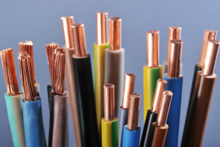
Materials: Copper vs Aluminium
Two metals dominate the market. Each carries trade-offs worth understanding before signing off a panel design.
Copper
Copper is the default choice across UK switchgear. The reasons are well established:
- High electrical conductivity (around 1.72 µΩ·cm at 20°C)
- Good mechanical strength at elevated operating temperatures
- Resistance to oxidation at joints
- Mature jointing and termination techniques
Common grades seen in panel work are C101 (electrolytic tough pitch, CW004A) and C103 (oxygen-free, CW008A), both specified to BS EN 13601 for drawn rod and bar.
Aluminium
Aluminium offers roughly 60% of copper’s conductivity at around a third of the weight, and at lower material cost. Grades 6101 and 1350 are typical. The trade-offs are:
- A larger cross-section is needed for the same ampacity (about 1.5 to 1.6 times bigger)
- An insulating oxide layer forms almost immediately on exposure to air
- Joints need bimetallic transition washers or pre-plated faces when meeting copper terminations
Mixing the two metals directly creates a galvanic cell. The result is corrosion, rising contact resistance and eventually a hot spot. The Copper Development Association publishes solid jointing guidance worth bookmarking.
Current Ratings: How Continuous Ampacity Is Set
The rated current (Ie) is the current the conductor can carry continuously without exceeding its specified temperature rise. The figure is not a simple table lookup. It depends on:
- Cross-sectional area and material grade
- Surface finish (bare, tinned or painted; emissivity affects radiation losses)
- Mounting orientation (vertical edgewise typically derates to about 85% of horizontal flat)
- Ambient temperature inside the enclosure
- Proximity of parallel bars and any ferrous parts (skin effect and proximity effect)
- Enclosure ventilation
What the Standard Actually Says
BS EN 61439-1 Table 6 sets temperature-rise limits referenced to a mean 24-hour ambient of 35°C. For bare conductors (Row b), the rise is limited by the mechanical strength of the material. Note g places an absolute ceiling of 105 K above ambient. In practice, designers work to a more conservative target of around 70 K rise to give margin for joints and to extend service life.
One point that often trips people up: current density is not a mandated figure in BS EN 61439-1. The standard governs the outcome (temperature rise verified by test, calculation or comparison), not the input. The industry rule of thumb of 1.5 to 2.5 A/mm² for enclosed copper conductors is design practice from manufacturer guides and the Copper Development Association, not a regulatory value.
A Practical Example
A 1600 A copper riser might be specified using an 80 x 10 mm cross-section per phase as a starting point. That is indicative only. The actual rating must be derated and verified by test or calculation once enclosure ventilation, mounting orientation and ambient conditions are accounted for. Always work to the assembly manufacturer’s verified design data, not rules of thumb from a website.
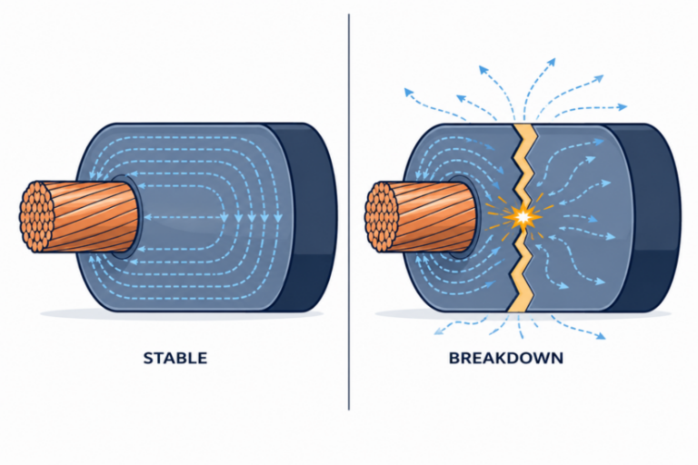
Short-Circuit Withstand: The Spec That Stops Panels Exploding
Continuous current rating tells you how the system behaves on a normal Tuesday. Short-circuit withstand tells you what happens on the worst day of its life.
When a fault occurs, prospective fault currents in UK LV systems can reach 16 kA, 25 kA, 50 kA or higher at the origin of the installation. Two distinct stresses act on the conductor.
Thermal Stress (Icw)
This is the rated short-time withstand current. Heat builds adiabatically because there is no time for dissipation. The standard equation is:
A ≥ (I × √t) / k
Approximate k values:
- 143 for copper (90°C initial to 250°C final)
- 94 for aluminium for the equivalent temperature range
This is the same form of equation used in BS 7671 Section 434 for fault current protection of conductors, and in IEC 60865-1 for short-circuit calculations.
Electrodynamic Stress (Ipk)
This is the rated peak withstand current. Parallel current-carrying conductors attract or repel each other with a force proportional to I². At 50 kA peak, that force can exceed several hundred newtons per metre, easily enough to tear an unbraced bar out of its supports.
Ratings are typically stated as, for example: Icw = 50 kA for 1 second, Ipk = 105 kA.
These figures must equal or exceed the prospective fault current at the point of installation. They are also tied directly to BS 7671 Section 434, which requires the upstream protective device to clear the fault within a time the conductor can withstand thermally.
The Health and Safety Executive has investigated multiple incidents where modified switchgear has failed under fault conditions. Arc-flash injuries from poorly braced assemblies remain a real-world hazard, not a theoretical one.
Where You Will Encounter Busbars on Site
Most working sparks meet a busbar system in one of these contexts:
- Main switchboards and Form 2, 3 or 4 distribution panels per BS EN 61439-2 Annex AA.
- Final distribution boards (the chocolate-bar conductor inside a consumer unit is the smallest everyday example).
- Busbar trunking systems for lighting drops and rising mains.
- EV charging hubs, particularly DC bars at higher-rated installations.
- Battery energy storage systems, now governed by Chapter 57 of BS 7671:2018+A4:2026.
- Medical locations, where EBBs are detailed in Section 710 and in HTM 06-01 (NHS Health Technical Memorandum).
- Earthing systems, including the MET and supplementary bonding terminals.
Practical Pointers for Installers
A few habits separate competent panel work from the kind that fails infrared inspection.
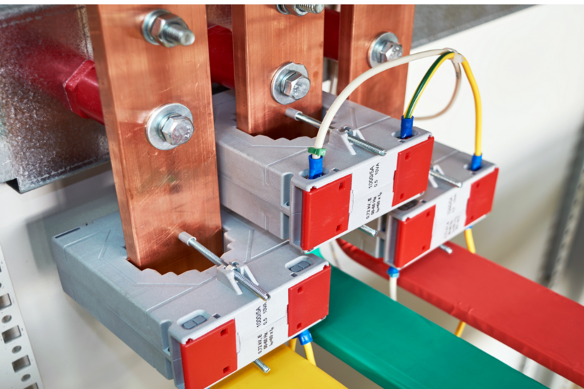
Joints and Torque
- Torque every bolt to the manufacturer's stated value, using a calibrated torque wrench
- Under-torque overheats. Over-torque damages the conductor and creeps as it cools
- Tin-plated or silver-plated faces give lower contact resistance and resist oxidation
- Bare-on-bare joints need cleaning with a non-loading abrasive immediately before assembly
- Use joint compound only where the manufacturer's design calls for it
Modifications and Verification
- Never improvise a tap-off on a tested assembly.
- Refer back to the original manufacturer or use a qualified panel builder to verify any modification against BS EN 61439.
- After modification, complete the inspection and testing requirements in BS 7671 Part 6, supported by the IET Code of Practice for Inspection and Testing.
Safety and Maintenance
- Prove dead using safe isolation methods per HSE Guidance Note GS38 before opening any panel.
- Schedule thermal imaging at six or twelve-month intervals. Loose joints show as hot spots long before they fail.
- Record findings and feed them back into the maintenance plan.
Busbars appear in more places than many installers expect, and details matter on every job. Keep sharpening your electrical skills with TradeFox and stay ready for the work you face on site every day.
Final Word
A busbar looks like a plain piece of metal. It is not. It is an engineered conductor verified against thermal, mechanical and short-circuit performance criteria. Every aspect of how it is mounted, jointed and protected affects whether the assembly is safe to energise.
Treat the system with the respect the standards demand. Never modify a tested assembly beyond the manufacturer’s documented limits. Work within the Electricity at Work Regulations 1989, keep current copies of BS 7671:2018+A4:2026 and BS EN 61439 to hand, and check the IET, BSI and NICEIC for technical updates and CPD.