


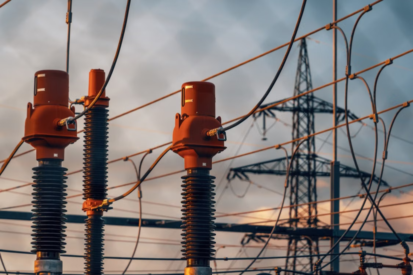
A surge arrester earns its keep in microseconds. Most of its life it sits on the structure drawing a trickle of leakage current and doing nothing you’d notice. Then lightning hits the overhead line, or a breaker slams open upstream, and the unit has to clamp a fast voltage spike and shunt the energy to earth before it reaches the transformer behind it.
Get the rating or the mounting wrong and one of two things happens: the arrester fails early, or it lets enough surge through to wreck plant that costs more than the rest of the bay. This one’s for people working on HV networks and those training into the trade, not for domestic gear.
What a Surge Arrester Does on an HV Network
Modern HV units are gapless metal oxide surge arresters, still called lightning arresters on plenty of older drawings. Inside the porcelain or silicone-rubber housing sits a stack of zinc oxide varistor blocks with a sharply non-linear voltage-current curve. Below its continuous operating voltage the unit behaves almost like an insulator and passes a fraction of a milliamp. Push the voltage past that threshold and the blocks turn strongly conductive, holding the voltage down to a residual level while thousands of amps run to earth.
Two numbers define the unit:
- Uc, the continuous operating voltage: Also written MCOV. BS EN IEC 60099-5 recommends it sits at least 5% above the highest continuous phase-to-earth voltage the unit will ever see. Set it too low and the blocks cook under normal running.
- Ur, the rated voltage: This isn't a voltage you can hold forever. It's the reference every other figure is tied to, and it maps to a 10-second temporary overvoltage capability. The full withstand is a voltage-against-time curve, so a one-second excursion is tolerated at a higher level than a thirty-second one.
Pick both against the real system voltage and earthing arrangement, not a round number that looks close enough. Oversizing Ur isn’t free either, because a higher-rated unit gives a higher residual voltage and eats into your protective margin.
Placement Decides How Much Protection You Get
Separation Distance
A surge arrester only guards a narrow zone around itself. The further the protected kit sits from it, the worse the protection, because a fast surge travels down the connection at close to the speed of light, reflects off the transformer winding and can almost double at the terminals. One substation study of a large EHV transformer found that a separation of about 30 m let the terminal voltage climb past the transformer’s basic insulation level. That figure isn’t a fixed limit though. It shifts with surge steepness, system voltage, the arrester’s residual voltage and how much BIL margin you’re working with.
Lead Length and Mounting
- Mount it close: Keep the unit as near the protected terminal as the layout allows. In a compact substation that's usually somewhere between about 0.5 and 3 m from the transformer HV bushing.
- Keep leads short: Both the line lead and the earth lead add an inductive voltage drop during a fast surge, and that voltage stacks on top of the residual voltage. Length drives it, not conductor diameter, so a fat cable run the long way round won't save you.
- Protect the transformer directly: An arrester out on the incoming bus catches line surges, but on its own it leaves the transformer open to reflection at its own terminals. The transformer is the expensive bit, so it gets its own unit.
If a road, an access route or phase spacing forces the arrester further out than you’d like, that’s a design decision that needs a separation calculation behind it, not a shrug.
Energy Rating, and Why the Old Class Numbers Changed
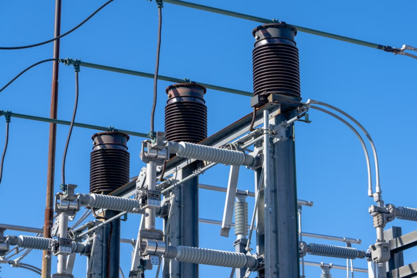
Older kit and older drawings talk about line discharge class 1 to 5. That system is being retired, though you’ll still meet it across the installed base. IEC 60099-4 Edition 3.0, published in 2014, dropped line discharge class and moved to charge and energy figures:
- Wth, the thermal energy rating: Quoted in kJ per kV of Ur.
- Qth and Qrs: The thermal and repetitive charge transfer ratings, both given in coulombs.
The same edition split the product world into station class and distribution class arresters, with distribution units graded light, medium and heavy (DL, DM, DH). In rough terms, an 11 kV feeder pole gets a distribution arrester, while a 132 kV substation gets a station class unit built for far higher energy duty.
Watch Cable-Fed Plant
The figure that trips people is switching energy on cable-fed transformers. Energising a transformer through a length of cable can throw an indicative 6 to 8 kJ/kV at the arrester, which is enough to leave a standard distribution unit under-rated. Capacitor banks and long lines pile repetitive stress on top. When the sums land near a class boundary, size up. The cost gap between two classes is small next to a transformer replacement.
How a Surge Arrester Fails, and the Signs on Site
Why They Fail
Almost every failure mode ends the same way: an internal short circuit that drops a line-to-earth fault onto the system. What changes is how it gets there. The main mechanism is thermal runaway. If the unit absorbs more energy than it can shed, or it sits under a temporary overvoltage that hangs around too long, the blocks heat up. Hotter blocks leak more current, which heats them further, and past a certain point the unit can’t recover. It ends up unable to hold even its normal operating voltage and short-circuits.
Block ageing gets blamed a lot, but modern zinc oxide chemistry is stable enough that gradual ageing rarely kills a unit on its own. Moisture past a failed seal does far more damage in the field, and so does heavy pollution on the housing.
Signs on Site
- Rising leakage current: A slow climb over time, mostly in the resistive component. Online monitors and third-harmonic meters exist to catch this.
- A jumped surge counter: A reading well beyond what the site history suggests.
- A dropped disconnector: On distribution units, a ground-lead disconnector that has operated and left the earth lead hanging clear.
- Visible damage: Discolouration, cracking, surface tracking, or a thermal-camera hotspot on the housing.
- Pressure-relief operation: On porcelain units, a split housing, expelled internals or debris on the plinth.
- Protection lockout: On a substation arrester, failure often shows first as protection operating and the bay tripping out.
Treat It as Live
One safety line here isn’t optional. A failed surge arrester is a faulted phase to earth until proven otherwise. Isolate, prove dead and apply earths before anyone goes near it, and don’t walk up to a shattered porcelain unit assuming the energy has gone. Work strictly to your own safe system of work, and to the permit or sanction-for-test that governs the job. The general principle never overrides your site’s documented procedure.
What UK Standards and Regulations Expect
Two technical standards carry the detail:
- BS EN IEC 60099-4: The product standard for gapless metal oxide arresters.
- BS EN IEC 60099-5: Selection and application, covering MCOV, temporary overvoltage and energy sizing.
Insulation coordination, matching the arrester’s protective level to the plant’s withstand level, runs off the IEC 60071 series. DNO and transmission specifications sit on top of these, and National Grid’s arrester specification, for one, calls up BS EN 60099-4 and sets out how units are configured at 66 and 132 kV.
Two sets of regulations frame the work in Great Britain. The Electricity Safety, Quality and Continuity Regulations 2002 place general duties on duty holders, network operators and their contractors alike, for the safe operation of the system, and sound overvoltage protection is part of meeting them. The Electricity at Work Regulations 1989 govern the people doing the job, so the isolation, proving dead and earthing described above sit directly under them. Neither one names a specific arrester, which is why the standards above are how you show the choice was sound.
HV electrical work demands careful preparation and safe working practices. TradeFox provides guided electrical and safe-isolation simulations that let you practise key skills at your own pace.
What Good Practice Looks Like
None of this works as a tick-box. Matching a surge arrester to the job means lining up system voltage, earthing, expected overvoltages, pollution level and the plant’s BIL, then mounting the unit close and leading it short. Do that and it sits quietly for years. Skip it and you find out the hard way, usually in the middle of a storm.