Every electrical distribution network relies entirely on the integrity of its connections. Constructing reliable cable terminations for medium and high voltage systems is a highly technical skill that demands absolute precision. When an electrical joint fails, the financial costs of unplanned downtime and the physical risks of arc flash are severe. The silent mechanism behind the majority of these catastrophic failures is partial discharge.
This technical guide breaks down the precise installation defects that initiate partial discharge and explains how strict adherence to standard procedures prevents early network degradation.
UK Regulatory Framework And Competence Requirements
Safety and technical competence are not optional in the high voltage sector. The Electricity at Work Regulations 1989 dictate that all electrical systems must be constructed, maintained, and operated to prevent danger. Regulation 16 specifically mandates that persons undertaking technical work must possess the technical knowledge or experience necessary to avoid danger to themselves and others.
While BS 7671 covers low voltage installations, erecting medium and high voltage equipment demands strict adherence to BS EN 61936-1. Executing flawless electrical connections requires more than formal training. Tradesmen must hold specific authorization from the relevant Distribution Network Operator to work on utility networks. They must strictly follow specific engineering recommendations, such as G81 frameworks, to ensure total compliance.
The Physics Of Partial Discharge
Tradesmen must understand the physics of the materials they handle to prevent joint failure. Partial discharge is a localized dielectric breakdown of a small portion of a solid or fluid electrical insulation system under high voltage stress. It does not bridge the complete space between two conductors. It acts as an electrical friction that slowly erodes the insulation from within.
Microscopic electrical sparks occur within trapped air voids or across the surface of the insulation. These tiny arcs generate heat, ultraviolet light, and ozone. This chemical and thermal degradation gradually destroys the cross-linked polyethylene insulation over months or years. The tracking path grows until the insulation can no longer hold back the voltage, resulting in a full short circuit.
Critical Defects During Preparation And Assembly
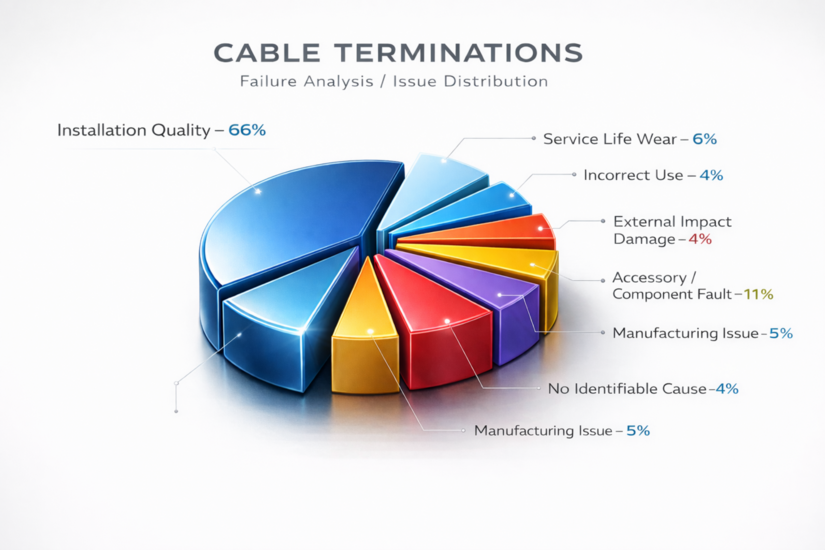
The majority of partial discharge issues are introduced by the jointer during the preparation phase. Eliminating these defects requires a systematic approach to every single cable preparation step.
Incorrect Semi-Conductive Screen Removal
Medium voltage cables utilize an extruded semi-conductive layer to equalize electrical stress across the insulation. Removing this layer precisely is the most unforgiving phase of the job. Jointers must use calibrated, specialist stripping tools.
Using a standard utility knife or a poorly adjusted peeling tool guarantees component failure. If the blade scores the underlying cross-linked polyethylene insulation by a fraction of a millimetre, it creates a microscopic air gap. Electrical stress concentrates heavily at this score mark under high voltage. This concentrated field initiates internal partial discharge, creating a carbonized tracking path that inevitably leads to a blowout.
Moisture And Particulate Contamination
Electrical joints must be assembled in highly controlled conditions. Dust, dirt, metal shavings, and moisture fundamentally alter the dielectric properties of the insulating materials.
- A single drop of sweat or a spot of rain falling onto the prepared insulation surface introduces highly conductive salts.
- Heat shrink or cold shrink tubing applied over this contamination permanently seals the moisture inside.
- High electrical fields exploit these microscopic contaminants and cause surface tracking along the boundary between the insulation and the applied tubing.
Tradesmen must use dedicated, lint-free cleaning wipes soaked in approved zero-residue solvents. Wiping must only occur in one direction, moving from the clean insulation towards the semi-conductive screen.
Misalignment Of Stress Control Components
The electrical field is no longer contained uniformly within the cable at the exact point where the semi-conductive screen is cut back. The field lines flare outwards violently, creating intense electrical stress. Jointers apply stress control tubing or high-permittivity mastic to manage this field.
These materials possess specific refractive properties that smooth out the electrical field lines and prevent flashover. It is absolutely crucial to differentiate between mastic types. Yellow high-permittivity mastic is strictly for stress control at the screen cutback. Red or black mastic is standard void-filling material used solely for environmental sealing at the lug or breakout. Conflating the two guarantees an immediate blowout upon energization.
If the tradesman positions the stress control tube incorrectly or leaves a physical gap, a void is created right at the point of maximum electrical stress. The air within this void ionizes immediately upon energization, causing severe and rapid partial discharge. Accurate measurement is non-negotiable.
Insufficient Clearances And Poor Shed Placement
The physical distance between the live high voltage lug and the grounded metallic shield must meet strict specifications.
- If the outer anti-tracking tubing is cut too short, the creepage distance is fundamentally compromised.
- Cable terminations installed in highly polluted outdoor environments or coastal areas require the correct number of weather sheds.
- Installing sheds upside down allows water to pool near the high voltage connection.
Failing to install the correct weather sheds leads to surface partial discharge. Electrical current creeps along the polluted outside layer of the termination, eventually burning a highly conductive carbon path directly to earth.
Tradefox can also help you understand the fundamentals, including safe isolation and basic electrical principles, so you can follow test results and site conversations with more confidence.
Testing And Verification Protocols
Visual inspection cannot detect internal voids, microscopic score marks, or incorrect mastic application hidden beneath shrink tubes. Verifying the integrity of completed cable terminations requires specialized high voltage testing equipment.
Very Low Frequency testing combined with partial discharge monitoring provides a clear, data-driven picture of the installation quality. Baseline partial discharge readings should be taken immediately after the installation is complete and before the network is put under full commercial load. Readings are measured in picocoulombs.
Acceptable picocoulomb limits are defined strictly by IEEE 400.2 standards and specific Distribution Network Operator guidelines. If the test results exceed these acceptable limits, the installation is fundamentally flawed. It must be cut out and entirely remade.
Constructing reliable infrastructure at medium and high voltages demands absolute respect for the physical properties of electricity. Every single step requires precision, environmental control, and exact adherence to technical instructions. Professional tradesmen can execute installations that ensure maximum network reliability and total compliance with UK safety standards by understanding the mechanics of partial discharge.